Analog Input Module
The Analog Input Module takes an analog signal from a hardware port, scales it and makes the scaled result available in its output register, allowing you to measure and store analog information (for example, the output of a transducer that is measuring steam pressure).
Module icon
![]()
Overview
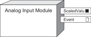
NOTE: The registers and settings available in this module depend on the device or node you are configuring, as well as its firmware and template versions. Not all registers or settings are available on all devices or the Virtual Processor, and labels may vary.
Inputs
Analog Input Modules have no programmable inputs
Setup registers
The Analog Input Module’s setup registers allow you to define a scaling factor for the values taken from the hardware port, and select the hardware input port.
 Zero Scale
This numeric bounded register defines what value appears in the ScaledValu output register when the minimum value of the supported nominal range for the hardware is applied.
 Full Scale
This numeric bounded register defines what value appears in the ScaledValu output register when the maximum value of the supported nominal range for the hardware is applied.
 Port
Port
This enumerated register defines which hardware port is providing the signal. Refer to the appropriate device User Guide for a list of available ports.
 Mode
Mode
This enumerated register defines whether the hardware port is configured to monitor current or voltage.
notice
EQUIPMENT DAMAGE
- Ensure the analog input is configured for the correct voltage or current mode before connecting or activating the current transducer.
- Do not exceed the device’s ratings for maximum limits.
Failure to follow these instructions will result in equipment damage.
 Update Rate
This enumerated register defines how frequently the ScaledValu output register is updated (one second or high-speed/half-cycle).
Output registers
 ScaledValu
This numeric register contains the scaled version of the hardware input (as defined by the Zero Scale and Full Scale setup registers).
 Event
Event
Events produced by an Analog Input Module are written into this register. Possible events and their associated priority value are shown in the following table:
| Event priority group | Priority | Description |
|---|---|---|
| Setup Change | 10 | Input links, setup registers or labels have changed. |
The Event output register stores the following information for each ION event: time stamp, priority, cause, effect, and any values or conditions associated with the cause and effect.
Detailed module operation
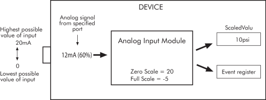
The figure below illustrates the operation of an Analog Input Module. The hardware port presents the module with a percentage value relative to the hardware limits. The Analog Input module then takes the percentage and maps it to the Zero Scale and Full Scale range. The result is written to the ScaledValu output register.
ScaledValu = % of input value * (Full Scale - Zero Scale) + Zero Scale
In this example, the input coming from the port is 50% of the possible input value. The Analog Input module takes this value and calculates what it corresponds to on the new scale. In this case, 50% on the new scale is the value 75.
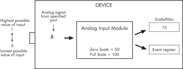
In most cases the output range of the sensor feeding the analog input matches the hardware limits of your device’s analog input port, so that the Full Scale and Zero Scale are the same as the sensor’s represented range.
| Analog sensor | Device’s analog input | Analog Input Module |
|---|---|---|
| 0-50 psi represented by 4-20 mA signal | 4-20 mA analog input range |
Full Scale = 50 (psi) Zero Scale = 0 (psi) |
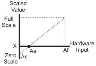
If the sensor’s output range does not match your device’s hardware limits, you must calculate the Full Scale and/or Zero Scale value by analyzing the system. The relationship between the hardware input and scaled output is linear, so a graph can represent the six points used to produce the operation:
|
|
| Aa | The lowest reading in the nominal operating range that is measured by the meter’s analog input port. |
| Af | The highest reading in the nominal operating range that is measured by the meter’s analog input port |
| Ax | The analog input source minimum value |
| X | The scaled equivalent of Ax |
The mathematical relationship between the values is show by the following equation:

Solving for Zero Scale:

Example:
An analog input module is linked to a 0 to 20 mA hardware port to monitor a steam pressure sensor ranging between 0 to 20 psi. The pressure sensor signal is 4 to 20 mA.
- Aa = 4 mA
- Af = 20 mA
- Ax = 0 mA
- Full Scale = 20 psi
- X = 0 psi
Calculate the Zero Scale setup register value:
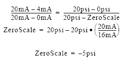
The Analog Input Module setup registers are programmed as follows:
- Full Scale = 20 psi
- Zero Scale = –5 psi
This will produce a 0 to 20 psi output represented by a 4 to 20 mA signal.
Responses to Special Conditions
The following table summarizes how the Analog Input Module behaves under different conditions.
| Condition | Response of Output Register |
|---|---|
| When the device is started or powered-up (either the first time or after a shut-down) | The Output register’s value matches the value at the Analog Input port on the connected device. |