Analog Output Module
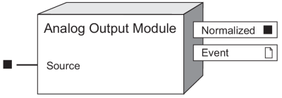
The Analog Output Module takes a Source input value and scales it to the appropriate values for output to an analog hardware port.
Module icon
![]()
Overview
The Analog Output Module also provides the scaled value as an output register that can be accessed by other modules.
 warning
unintended operation
| ● | Do not use ION devices or software for critical control or protection applications where human or equipment safety relies on the operation of the control circuit. |
| ● | Match analog output wiring polarity to the external analog device’s polarity. |
Failure to follow these instructions can result in death, serious injury, or equipment damage.
NOTE: The registers and settings available in this module depend on the device or node you are configuring, as well as its firmware and template versions. Not all registers or settings are available on all devices or the Virtual Processor, and labels may vary.
Inputs
 Source
The Analog Output module takes the value of this input, scales it and sends it to a hardware port. It must be a numeric register from another module’s output registers. Linking this input is mandatory.
Setup registers
The Analog Output Module’s setup registers are used to define a scaling factor for the Source value, and select the hardware output port and the output signal type (voltage or current).
 Zero Scale
This numeric bounded register should be set to the Source input value that corresponds to the minimum possible output on the analog hardware port.
 Full Scale
This numeric bounded register should be set to the Source input value that corresponds to the maximum possible output on the analog hardware port.
 Port
Port
This enumerated register defines which hardware port will output the signal. Refer to the device’s documentation for a list of available ports..
 Mode
Mode
This enumerated register defines whether the hardware port is configured to output voltage or current.
notice
EQUIPMENT DAMAGE
- Ensure the analog input is configured for the correct voltage or current mode before connecting or activating the current transducer.
- Do not exceed the device’s ratings for maximum limits.
Failure to follow these instructions will result in equipment damage.
Output registers
 Normalized
This numeric register contains a normalized value (i.e. between 0 and 1) proportional to the output range on the analog hardware port. For example, if the Source input is 50 and the Zero Scale and Full Scale setup registers are set to 0 and 200 respectively, the value in the Normalized output register will be 0.25.
 Event
Event
Events produced by an Analog Output Module are written into this register
Possible events and their associated priority value are shown in the following table:
| Event priority group | Priority | Description |
|---|---|---|
| Setup Change | 10 | Input links, setup registers or labels have changed. |
The Event output register stores the following information for each ION event: time stamp, priority, cause, effect, and any values or conditions associated with the cause and effect.
Responses to special conditions
The following table summarizes how the Analog Output Module behaves under different conditions.
| Condition | Response of output registers |
|---|---|
| If the Source input is not available | The Output register holds the last value obtained while the Source input was available, or may go to zero (mA/V) for some devices. Refer to your device’s user documentation. |
| When the device is started or powered up (either the first time, or after a shutdown) | The Output register’s value matches the hardware port’s value. Supported analog output devices hold the lowest values in their operating range at power-up. Refer to the Technical Specifications for the analog output device you are using. |
Detailed module operation
The figure below illustrates the operation of the Analog Output Module. The Source input falls between the Zero Scale and Full Scale values. It is scaled to create the Normalized value and the result is sent to the specified hardware port (as defined by the Port setup register). The Normalized output register provides information about the state of the hardware; in this case, the output on the hardware port is at 83%.
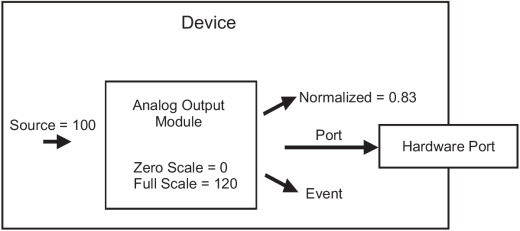
If at any point the input rises above the value specified in the Full Scale setup register, the Normalized register stays at its maximum value of 1 and the hardware analog port outputs its maximum range value. Likewise, if the input falls below the value specified in the Zero Scale register, Normalized register stays at its minimum value of zero and the hardware analog port outputs its minimum range value. If the Analog Output module is linked to a numeric source and that source changes to NOT AVAILABLE, the module's Normalized output register retains the last known value.
However, if the Analog Output Module's Source input is changed (re-linked) to a source that is NOT AVAILABLE, the module's Normalized output register changes to zero. If the Analog Output module goes offline or the module’s outputs go NOT AVAILABLE , the hardware analog port is zero (0 mA, 0 V) under most conditions.
Analog Output Calculations
The Analog Output Module takes the Source value and converts it to Normalized (a normalized value between 0 and 1) based on the Zero Scale and Full Scale values.

If your meter’s analog output has the same range as the analog sensor connected to the output, then your Zero Scale is your Source minimum value and Full Scale is your Source maximum value. For example if your meter’s analog output port has a range from 4 - 20 mA, and the sensor reading this analog port expects values in that range (4 - 20 mA).
The device’s analog hardware port produces voltage or current based on the Normalized percentage of the hardware port’s current or voltage range.

To calculate the input Source value from an analog hardware port value:

You only need to calculate the Zero Scale and Full Scale values if your meter’s analog output port has a different range than the sensor connected to it; for example if your meter has a 0 - 20 mA range and the sensor reading the analog output port expects values in the 4 - 20 mA range.
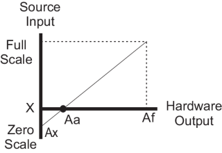
You can calculate the Full Scale and Zero Scale values by analyzing the system. The relationship between the Source input and the Normalized output is linear, so a graph can represent the six points used to produce the operation:
|
|
| Aa | the analog hardware output minimum range value. |
| Af | the analog hardware output maximum range value. |
| Ax | the analog hardware output minimum value (0). |
| X | the scaled equivalent of Aa. |
The mathematical relationship between the values is shown by the following equation:

Solving for Zero Scale

Calculation Example
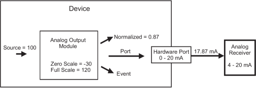
The meter is monitoring a 0 to 120 kW system. The receiving device can read a signal from 4 - 20 mA and your meter’s analog hardware output port has a 0 to 20 mA range. The Full Scale and Zero Scale registers need to be set up to scale the output accordingly. The variables for the module operation are:
- Full Scale = 120 kW
- X = 0 kW
- Af = 20 mA
- Ax = 0 mA
- Aa = 4 mA
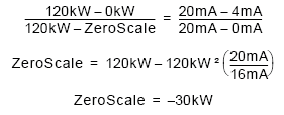
The Analog Output Module setup registers are programmed as follows:
- Full Scale = 120 kW
- Zero Scale = -30 kW
This will produce a 0 to 120 kW output represented by a 4 to 20 mA signal.
When the Source is 100, the Normalized output is:

The 0 - 20 analog hardware port outputs:
Analog output = 0.87 * (20 mA - 4 mA) + 4 mA = 17.87 mA
Calculation Example Diagram
