AND/OR Module
AND/OR Modules are flexible tools that allow you to logically link together Boolean registers.
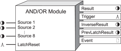
Module icon
![]()
Overview
Using the AND/OR Module, you can initiate an action based on the condition of a combination of these registers. A common application for this module is “ORing” multiple setpoints to the same Digital Output Module which may control a relay external to the device.
An AND/OR Module monitors a number of Boolean registers and performs an AND/ NAND or OR/NOR calculation on them. The calculation result, which is also a Boolean variable, is written into the Result register. For example, you may want to monitor the condition of three other Boolean registers and respond only if they are all ON at the same time. You can also control if the AND/OR Modules produce events.

NOTE: The registers and settings available in this module depend on the device or node you are configuring, as well as its firmware and template versions. Not all registers or settings are available on all devices or the Virtual Processor, and labels may vary.
Inputs
 Source 1 to Source 8
All AND/OR modules can have up to eight Source inputs. The AND/OR Module uses these inputs to calculate the Result output register. You can have multiple Source inputs for each AND/OR module.
NOTE: Different ION meters support a different number of Source inputs.
These inputs must be Boolean output registers from other modules. You only need to link the first Source input for the module to operate; linking the remaining inputs is optional.
 LatchReset
If the UpdateMode setup register is set to LATCHING, pulsing this register sets the PrevLatchResult value to be equal to the instantaneous value of the Result output register, and resets the Result output register.
Setup registers
 Mode
Mode
This register specifies the type of logical evaluation to be performed. It is an Enumerated register allowing you to select AND, OR, NAND or NOR.
 EvLog Mode
This register specifies if changes in the Result output register are recorded as events in the Event output register. If you select LOG ON, these events are logged. If you select LOG OFF, these events are not included in the Event output register. (Note that in either case, linking the module and changing setup registers are still logged as events in the Event register.)
 Update Mode
This register specifies whether the And/Or Module is LATCHING or INSTANTANEOUS. If you select INSTANTANEOUS, the PrevLatchResult output is N/A. If you select LATCHING, the Result output register will latch when true and the PrevLatchResult register will store the Result value from the latest LatchReset pulse.
NOTE: In LATCHING mode, the Result output register will latch when true, and remain true until it gets reset by a pulse on the LatchReset input.
Output registers
 Result
This Boolean register contains the result of the AND, OR, NAND, or NOR calculation. If Update Mode is set to LATCHING, this output will be calculated until it becomes TRUE, and will stay TRUE until LatchReset is pulsed.
 Trigger
Every time the Result output register changes from OFF to ON, the Trigger output register generates a pulse.
NOTE: No Trigger pulse is generated for ON to OFF transitions.
 InverseResult
This Boolean register contains the inverse (opposite) value to the instantaneous value of Result.
 PrevLatchResult
If Update Mode is set to LATCHING, this register contains the Result value when LatchReset was last pulsed. If Update mode is set to INSTANTANEOUS, this register value is N/A.
 Event
Event
Events produced by the AND/OR Module are recorded in the Event register.
Possible events and their associated priority numbers are shown in the following table:
| Event priority group | Priority | Description |
|---|---|---|
| Setup Change | 10 | Input links, setup registers or labels have changed. |
| Input Register Change | 15 | Boolean input has changed.* |
| Information | 25 | NOT AVAILABLE input caused output to go NOT AVAILABLE. |
* These events are only recorded if the EvLog Mode setup register is set to LOG ON.
The Event output register stores the following information for each ION event: time stamp, priority, cause, effect, and any values or conditions associated with the cause and effect.
Detailed module operation
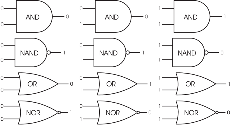
Depending on what you select for the module’s Mode setup register, the module performs the logical calculations as shown in the following diagrams (zeroes and ones represent Boolean OFF and ON conditions, respectively):

- The first row illustrates how the module operates an AND operation. The Result output will be ON only if all inputs are ON (Result is OFF if at least one input is OFF).
- The second row illustrates how the module operates a NAND operation. The Result output will be OFF only if all inputs are ON (Result is ON if at least one input is OFF).
- The third row illustrates how the module operates an OR operation. The Result output will be ON if at least one input is ON (Result is OFF only if all inputs are OFF).
- The last row illustrates how the module operates a NOR operation. The Result output will be OFF if at least one input is ON (Result is ON only if all inputs are OFF).
Using the module
The following steps outline how to use an AND/OR Module. It is not necessary to do these steps in order; for example, you could configure all the setup registers first, and then link to another module later.
- The first step in using an AND/OR module is to determine what values you want to compare, i.e. your Source inputs.
- The next step is to determine what kind of evaluation you want the module to perform. You can select AND, OR, NAND, or NOR via the Mode setup register.
- Changes in the Result output register can be logged by selecting the LOG ON option using the EvLog Mode setup register.
NOTE: Ensure that the Source inputs you choose all have the same update rate. If you mix high-speed and high-accuracy inputs, the AND/OR module operates at the slowest update rate.
Once you link an AND/OR Module to its sources, they are evaluated and the Boolean result is written into the Result output register. Every time the Result changes from OFF to ON, a pulse is generated in the Trigger output register.
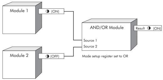
The example below illustrates how you can link an AND/OR Module to the Boolean output registers of two other modules.

Responses to special conditions
The following table summarizes how the AND/OR Module behaves under different conditions:
| Condition | Response of output registers |
|---|---|
| If the Source input is NOT AVAILABLE | The Result output register depends on Source input combinations (see the table below). |
| After the module is re-linked or its setup registers are changed | The Result output register is NOT AVAILABLE. |
| When the device is started or powered-up (either the first time, or after a shut-down) | The Result output register is NOT AVAILABLE. |
| Mode | AND/OR Module Behavior |
|---|---|
| AND | If any input is OFF, the output is OFF. If inputs are either ON or NOT AVAILABLE, the output is NOT AVAILABLE. |
| NAND | If any input is OFF, the output is ON. If inputs are either ON or NOT AVAILABLE, the output is NOT AVAILABLE. |
| OR | If any input is ON, the output is ON. If inputs are either OFF or NOT AVAILABLE, the output is NOT AVAILABLE. |
| NOR | If any input is ON, the output is OFF. If inputs are either OFF or NOT AVAILABLE, the output is NOT AVAILABLE. |