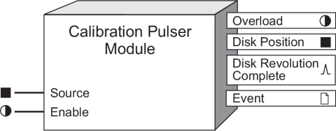
Calibration Pulser Module
The Calibration Pulser Module is a highly accurate energy pulser often used for verifying calibration on revenue-class ION meters.
Module icon
![]()
Overview
This module is typically used to connect the power outputs (for example, kW, kVAR or kVA) of the Meter Units Power Meter Module to the ION meter’s hardware output channel.
This module integrates the instantaneous power (in kW, kVAR or kVA) appearing at its Source input, then sends one complete pulse or KYZ transition to the output hardware channel each time the integrated power (i.e., the energy in Wh, VARh or VAh) reaches the value defined by the Kt (pulse weight) setup register.

NOTE: The registers and settings available in this module depend on the device you are configuring, as well as its firmware and template versions. Not all registers or settings are available on all devices, and labels may vary.
Inputs
 Source
All Calibration Pulser modules have one Source input. This numeric input is usually linked to the kW, kVAR, or kVA outputs from the MU Power Meter module. Linking this input is mandatory. The Source input must be in kW units (not Watts).
 Enable
This input enables or disables the Calibration Pulser module (by setting it to ON or OFF respectively). When disabled the module will not send pulses to the hardware channel specified in the Port setup register. This input is optional; if you leave it unlinked, the module is enabled by default.
Setup registers
 OutputMode
This register specifies whether the output signal is a complete pulse (PULSE) or a change of state transition (KYZ).
 Pulse Width
This register defines the output pulse ON time (i.e., how many seconds the pulse that is sent to the output hardware channel stays on). For example, this can correspond to the time period that an LED is lit.
 Kt (pulse weight)
This register defines the weight of the output pulse (i.e., how many energy units in Wh, VARh or VAh are accumulated before the module sends an output pulse to the hardware channel). A typical industry standard for energy pulsing is one pulse per 1.8 energy units (Wh, VARh or VAh). Kt units are measured in Watt-Hours.
 Int Mode
The following table describes the different integration modes for the Calibration Pulser:
| Mode | Description |
|---|---|
| forward | Used for imported energy – only positive Source values are considered for output pulsing. |
| reverse | Used for exported energy – only negative Source values are considered for output pulsing. |
| absolute | Used to obtain the absolute values of imported and exported energy - both positive and negative Source values are considered positive and added for output pulsing. |
| net | Used to obtain the difference between imported and exported energy (negative Source values are subtracted from positive Source values). For ION8800 meters, this mode acts the same as absolute mode. |
 Port
Port
This register specifies to which hardware port the output pulse is sent, usually an LED output for verification testing. Some meters have internal mechanical relays. Refer to your meter documentation for a list of available ports.
notice
HAZARD OF MISAPPLICATION (MISUSE)
Because mechanical relays have limited lifetimes, mechanical KYZ relays are typically not suitable for energy pulsing applications. For energy pulsing applications, consider using Form A outputs in KYZ mode.
Failure to follow these instructions will result in equipment damage.
Output registers
 Overload
This Boolean register turns ON if the pulse train duty cycle goes above 47.5% (i.e., if the pulse ON time becomes greater than the pulse OFF time).
 Disk Position
This register indicates how much energy has accumulated since the last time the module pulsed.
 Disk Revolution Complete
the value defined by the Kt setup register. This register is typically linked to hardware output port used for energy pulse counting.
 Event
Event
Any events produced by the Calibration Pulser Module are recorded in the Event register as follows:
| Event priority group | Priority | Description |
|---|---|---|
| Setup Change | 10 | Input links, setup registers or labels have changed |
The Event output register stores the following information for each ION event: time stamp, priority, cause, effect, and any values or conditions associated with the cause and effect.
Detailed module operation
The Calibration Pulser module is commonly used in energy pulsing applications. The module’s Source input is typically linked to the kW, kVAR or kVA output registers of the MU (meter units) Power Meter module.

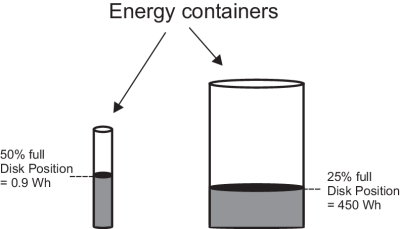
The Kt setup register defines the pulse weight, i.e., how much energy accumulates (in Wh, VARh or VAh depending upon its input) before the module sends a complete pulse or KYZ transition to the hardware channel specified in the Port setup register. In simple terms, the Kt setup register defines (in Watt-hours) the size of the container that collects energy. The Disk Position register indicates how much energy has been collected in this container (similar to a car’s fuel tank gauge).
For example, if you want the Calibration Pulser module to pulse once every time it accumulates 1.8 Wh of energy, you would enter a value of 1.8 in the Kt setup register. If you want to module to pulse once every time it accumulates 1.8 kWh of energy, you would enter a value of 1800 (since 1.8 kWh = 1800 Wh).

When the container is full, the module sends a pulse to the Disk Revolution Complete output register, and the container is emptied.
Output Mode: PULSE
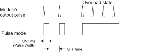
When the OutputMode setup register is set to PULSE, the module sends a complete pulse to the output hardware port each time the Kt value is reached.

In the above diagram, each trigger in the top graph (Module’s output pulse) represents one pulse sent to the Disk Revolution Complete output register. The bottom graph illustrates how the pulse appears at the output hardware channel. The Pulse Width setup register defines the ON time of this pulse. When the module is operating in Normal state, the output pulse’s duty cycle is less than 47.5%. If the output pulse’s duty cycle reaches 47.5% or above, the module goes into Overload state. When this happens, the Overload output register turns ON, the hardware channel remains ON, and the module does not send any more pulses to the output hardware channel. The module returns to Normal state when the duty cycle drops below 47.5%.
| Normal State (Normal pulsing) | Pulse duty cycle < 47.5% |
| Overload State (No pulse sent to output) | Pulse duty cycle > 47.5% |
The duty cycle for the output pulse is calculated as follows:

Duty cycle changes when the value at the Source input changes. Depending on the Kt and Pulse Width settings, the value appearing at the Source input causes the duty cycle to reach 47.5%. This maximum Source value (Max Source) can be calculated using the following formula:

For example, if you set the Kt register to 1800 (one pulse per 1800 Wh), and you set the Pulse Width to 0.05 seconds, the module will be able to support normal pulsing as long as the Source input does not exceed 61,560 W (calculated Max Source). The Overload output will turn ON when the instantaneous value at the Source input reaches or exceeds this value.
To prevent the module from going to Overload state, set the Pulse Width to just slightly greater than the minimum ON time period required for the output hardware channel (e.g. LED) to recognize it as a valid pulse. Otherwise, the pulse weight (Kt) setup register needs to be redefined (i.e. it needs to be increased).
Output Mode: KYZ
When the OutputMode setup register is set to KYZ, the module triggers the output hardware port to change state (i.e. changes its state from OFF to ON, and vice-versa) each time the Kt value is reached.
NOTE: For KYZ mode, the Pulse Width setup register defines the minimum amount of time that the output pulse must stay ON in order for the output hardware channel to recognize it as a valid pulse.

In the above diagram, each trigger in the top graph (Module’s output pulse) represents one pulse sent to the Disk Revolution Complete output register. The bottom graph illustrates how the KYZ transitions (changes of state) appears at the output hardware channel. In KYZ mode, the Pulse Width setup register is ignored; it is only used for calculating the maximum source value (i.e., Max Source, see formula below). The actual minimum pulse width that the Calibration Pulser is able to output before overloading will be Pulse Width/0.95. When the module is operating in Normal state, the output pulse triggers the hardware channel to change state (OFF to ON, or vice-versa). If the value at the Source input reaches the Max Source value, the module goes into Overload state. When this happens, the Overload output register turns ON, the hardware channel remains ON, and the module does not send any more KYZ transitions to the output hardware channel. The module returns to Normal state when the Source input drops below the Max Source value. This value can be calculated using the following formula:

For example, if you set the Kt register to 1800 (one pulse per 1800 Wh), and you set the Pulse Width to 0.050 seconds, the module will be able to support normal KYZ pulsing as long as the Source input does not exceed 123,120 W (calculated Max Source). The Overload output will turn ON when the instantaneous value at the Source input reaches or exceeds this value.
To prevent the module from going to Overload state, set the Pulse Width to just slightly greater than the minimum ON time period required for the output hardware channel (e.g. LED) to recognize it as a valid KYZ transition. Otherwise, the pulse weight (Kt) setup register needs to be redefined (i.e., it needs to be increased).