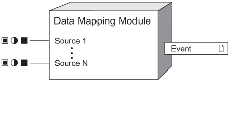
Data Mapping Module
The Data Mapping Modules define not only the Modbus data as described in your device’s Modbus register map, but also the values shown on the display and webpages.
Module icon
![]()
Overview
There are many types of Data Mapping Modules, and the module names and icons indicate the type of data being mapped. Data Mapping Modules are core modules which can be disabled to allow for custom Modbus mapping using Modbus Slave modules.
NOTE: These modules are configured to provide default Modbus values as described by the device’s Modbus map and define the values used on the device’s display and webpages, and they should not be modified beyond the procedures described in this document. Download your device’s Modbus map, available from www.se.com.
To provide additional values not included in your meter’s default Modbus map, use a Modbus Slave Module.

NOTE: The registers and settings available in this module depend on the device or node you are configuring, as well as its firmware and template versions. Not all registers or settings are available on all devices or the Virtual Processor, and labels may vary.
Inputs


 Source 1 .... N
These registers are connected to the output registers of other modules and define your device’s default Modbus map as well as the values shown on your device’s display and webpages. The quantity of Source inputs varies depending on the Data Mapping Module.
Setup registers
 Modbus Map Enable
This setup register enables or disables that Data Mapping Module’s Modbus functions (by setting it to yes or no respectively). This register does not impact the data displayed on your device’s display or webpages. When disabled, the values connected to the module’s inputs are no longer available to a Modbus master as described in the device’s default Modbus map, and the associated Modbus registers can be used by Modbus Slave Modules to create a custom Modbus map.
 Cfg Modbus Map Enable
This setup register enables or disables all default Modbus registers that are not mapped to a Data Mapping module. An example of this type of register is a setup register like Volts Mode (from the Power Meter module). This register does not impact the data displayed on your device’s display or webpages. When disabled, Modbus register values not linked to a Data Mapping Module are no longer available to a Modbus master as described in the device’s default Modbus map, and the associated Modbus registers can be used by Modbus Slave Modules to create a custom Modbus map.
Output registers
 Event
Event
All events produced by the Data Mapping Module are recorded in the Event register.
Possible events and their associated priority numbers are shown in the table below.
| Event priority group | Priority | Description |
|---|---|---|
| Setup Change | 10 | Input links, setup registers or labels have changed. |
The Event output register stores the following information for each ION event: time stamp, priority, cause, effect, and any values or conditions associated with the cause and effect.
Responses to special conditions
The following table summarizes how the Data Mapping Module behaves under different conditions.
| Condition | Response of output registers |
|---|---|
| When the meter is started or powered-up (either the first time, or after a shutdown). | All output registers retain the values they held when the meter was shutdown. |
Detailed module operation
The following table lists the possible Data Mapping Modules that may exist on your device:
| Icon | Data Mapping Module | Description |
|---|---|---|
|
|
Data Mapping Dmd Modules | Maps kW, kVA and kVAR demand data such as kW sd del (sliding demand kilowatts delivered) as well as current demand such as I a sd (sliding demand phase A current). |
|
|
Data Mapping Egy Modules | Maps kWh, kVAh and kVARh delivered and received data, including conditional, quadrant and incremental energies. |
|
|
Data Mapping EN Modules | Maps present interval EN50160 power quality compliance data. |
|
|
Data Mapping EN Prev Modules | Maps previous interval EN50160 power quality compliance data. |
|
|
Data Mapping I/O Modules | Maps input metering data, alarms, resets and reset counts. |
|
|
Data Mapping Meas Modules | Maps measured data from the standard and high-speed Power Meter module. The Cfg Modbus Map Enable setup register may exist in this module. |
|
|
Data Mapping PQ Modules | Maps power quality data such as Crest Factor, K Factor and total harmonic distortion, including IEC 61000-4-30 power quality compliance data. |
|
|
Data Mapping Stats Modules | Maps statistical low, mean and high data values, such as I a mean (phase A current average value). |
|
|
Data Mapping TOU Modules | Maps time-of-use (TOU) data, such as seasons, rates, and per-season demand such as kW sd rec A (sliding demand kilowatts received in season A). |
Creating a Custom Modbus Map
Specific ION data values can be mapped using Modbus Slave modules, even if they are already connected to a Data Mapping Module.
To create a custom Modbus map using registers that are assigned in the default map, you must make these registers available by disabling the associated Data Mapping module(s) before creating the custom map using Modbus Slave modules. The Modbus Slave Module will not go online if there are Modbus address register conflicts with a Data Mapping Module, and the Data Mapping Module will remain offline even if enabled if a Modbus address conflict is detected.
To create a custom Modbus map using registers that are defined in the default Modbus map but are not inputs to a Data Mapping Module, you must make these registers available by setting the Cfg Modbus Map Enable setup register (usually located in the Data Mapping Meas module) to disabled (no).