Data Recorder Module
Data Recorder Modules let you record and store different kinds of data.
Module icon
![]()
Overview
The module can be configured to start recording under a specified circumstance. Possible applications for Data Recorder Modules include power interruption analysis, historical trending, and creating coincidental Min/Max logs.
The Data Recorder Module records the values of its Source inputs each time its Record input is pulsed and stores them in the Data Log output register. The Data Log output register contains the Source values along with a timestamp indicating when the Record input was pulsed.
If you re-link any of the inputs or make any changes to the setup registers, the contents of the Data Log output register are cleared. To save the information, ensure that the data has first been uploaded before re-linking inputs or changing setup registers.
notice
data Loss
Ensure that all important data has been recorded before configuring data recording.
Failure to follow these instructions can result in data loss.
NOTE: The registers and settings available in this module depend on the device or node you are configuring, as well as its firmware and template versions. Not all registers or settings are available on all devices or the Virtual Processor, and labels may vary.
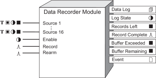
Inputs


 Source
These registers are the inputs whose values are recorded. Each time the Record register is pulsed, the values of the Source registers are stored in the Data Log output register. There are sixteen Source registers. The following are the types of registers that the Source inputs can be linked to:
- For ION meters, Source inputs can be linked to Boolean, numeric or numeric bounded registers.
- For the Virtual Processor, Source inputs can be linked to Boolean, numeric, numeric bounded or string registers.
You must link the first Source input for the module to operate. Linking the remaining Source inputs is optional.
 Enable
This register enables or disables the Data Recorder module (by setting it to on or off respectively). If you disable a Data Recorder module, it disregards pulses to the Record input. Linking this input is optional; if you leave it unlinked, the Enable input defaults to on and the module still operates.
 Record
When this register is pulsed, the source inputs are copied to the Data Log output register. If the RecordMode setup register is set to stop-when-full, and the Data Log register is full, no data will be copied. Linking this input is mandatory.
notice
EQUIPMENT DAMAGE
- If you increase the rate that Record is pulsed from the factory default setting, it may cause premature failure of the meter’s flash memory.
- Do not modify this register and connected modules without a thorough understanding of the impact on the meter’s flash memory.
Failure to follow these instructions can result in premature flash memory failure.
 Rearm
Rearm
When this register is pulsed and the RecordMode setup register is set to stop-when-full, the Data Recorder module resets to allow full capacity. If the RecordMode setup register is set to circular, pulses on the Rearm input are ignored. The Rearm input must be linked if the module’s RecordMode setup register is set to stop-when-full. Pulsing the Rearm input resets the log so that new records can be recorded. If the Rearm input is not pulsed, no new records are loaded into the log.
NOTE: Rearm can be left unlinked only if circular mode is used exclusively.
Setup registers
The setup registers of the Data Recorder Module determine how much information the module can store.
 Depth
Depth
This numeric bounded register determines the maximum number of entries in the output log. You must enter a value here in order for the Data Recorder Module to function.
Depth must be an exact multiple of the sum of Pre-trigger Records + Post-trigger Records + 1 (where 1 is the actual record when the triggered recording occurred). Refer to “Pre-trigger Records and Post-trigger Records: detailed operation” for more information.
 RecordMode
This register determines the recording mode, defining what happens when the Data Log output register is full. If you select circular, the newest values get recorded and the oldest are dropped (FIFO). If you select stop-when-full, the Data Recorder module stops writing new values into the Data Log output register when it reaches its depth.
NOTE: When RecordMode is set to stop-when-full, each Data Recorder module’s Rearm input should be linked to an exclusive pulse register (i.e. the pulse register is NOT shared with other Data Recorder modules). Sharing a pulse register with multiple Data Recorder Rearm inputs can lead to loss of logged data.
 Insert Outage Records
This setup register allows you to decide how the meter handles logged information after a power outage. For more information, refer to “Insert Outage Records: Detailed Operation”.
NOTE: The Insert Outage Records functionality does not function if the buffer depth is set to less than the log depth. In order to use this functionality, make sure that the buffer depth is set to equal to or greater than the log depth.
 LogMode
This register determines how the logged data is backed up so that it can be recovered if the device loses power. In most logging applications, this register should be set to normal. If data is being continuously logged at a high rate, select high speed continuous.
 Checksum
This register enables or disables checksum data validation. Enabling this register stores a checksum with each record. If the checksum and the data record do not match, the invalid data cannot be retrieved, and an event is generated for each attempt to read the invalid data. These events continue until the data recorder is reset or the invalid data is overwritten.
 Buffer Depth
This register sets the maximum number of records that can be stored in the meter’s short-term RAM for the log before they are replicated to the meter’s long-term memory.
Buffer Depth must be an exact multiple of the sum of Pre-trigger Records + Post-trigger Records + 1 (where 1 is the actual record when the triggered recording occurred). Refer to “Pre-trigger Records and Post-trigger Records: detailed operation” for more information.
NOTE: Setting Buffer Depth to a value equal to or greater than the log depth instructs the meter to copy (rather than move) log entries from short-term to long-term memory.
 Timestamp Mode
This register specifies the timestamp resolution for the triggered recording:
- record pulse uses the meter clock time with millisecond resolution.
- round to nearest second adjusts the timestamp for 1-second resolution, where the triggered recording time is rounded to the nearest second.
- round to nearest minute adjusts the timestamp for 1-minute resolution, where the triggered recording time is rounded to the nearest minute.
Refer to “Timestamp mode: detailed operation” for more information.
 Pre-trigger Records
This register specifies how many pre-event records are captured and saved with each triggered recording. Pre-event records are buffered log data records that immediately precede the triggered recording.
 Post-trigger Records
This register specifies how many post-event records are capture and saved with each triggered recording. Post-event records are buffered log data records that immediately follow the triggered recording.
Output registers
 Data Log
This register contains a log of the Source input values, recorded each time the Record input is pulsed. Its capacity is determined by the setup registers.
 Log State
This register indicates when the Data Log register is full. If the RecordMode setup register is set to stop-when-full and the Data Log register has reached its depth, this register is on (its default on label is Full). When the RecordMode setup register is set to circular, or when the RecordMode is set to stop-when-full but the Data Log register has not yet reached its depth, the Log State register is off (its default off label is Not Full).
 Records Left
When the RecordMode setup register is set to stop-when-full, the Records Left register indicates the number of additional data records that this module can store before it becomes full. If this register contains a negative value, it indicates the number of times the module was triggered after being full. When the RecordMode setup register is set to circular, this register is not available.
 Record Complete
This register will generate a pulse when the data at the Source inputs is successfully recorded.
 Buffer exceeded
This register indicates the number of records lost, in a situation where the buffer is exceeded.
 Buffer remaining
This register indicates how much of the buffer (number of records) is unused to help determine when the data recorder is nearing the limit of its buffer capacity.
 Event
Event
All events are recorded in the Event register.
Possible events and their associated priority numbers are:
| Event priority group | Priority | Description |
|---|---|---|
| Setup Change | 10 | Input links, setup registers or labels have changed. |
| Failure | 255 | Bad data record found (checksum does not match data). |
The Event output register stores the following information for each ION event: time stamp, priority, cause, effect, and any values or conditions associated with the cause and effect.
Responses to special conditions
This table summarizes how the module acts under different conditions.
| Condition | Response of output registers |
|---|---|
| If the inputs are not available | All output registers hold the last values obtained when inputs were available. |
| If the Enable input is off | The Data Log register retains the data that was logged before the Enable input became false. The Log State register is unaffected. |
| After the module is re-linked or its setup registers are changed | All logged data in the Data Log register is deleted. |
| When the device is started or powered-up (either the first time or after a shutdown) | The Data Log register retains the data it held at shutdown. |
Detailed module operation
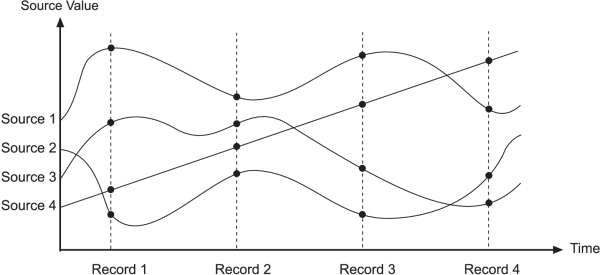
The figure below shows an example of a Data Recorder module recording the values of four Source inputs. Each time the Record input receives a pulse, the values of the Source registers (represented by the black dots) are copied into the Data Log output register along with a timestamp indicating when the Record register was pulsed.
Linking source inputs
When choosing the Source inputs for this module, you should make sure that they all have the same update rate. If you link one input to a high-speed module, and then link another to a module with a slower update rate, the Data Recorder module may give unexpected results. Consider the diagram below:
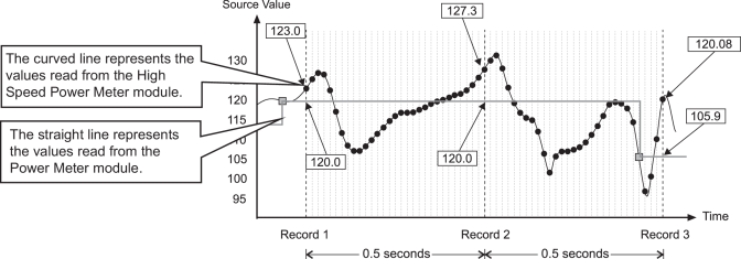
In this example, the Data Recorder has been set to record every 0.5 seconds. The black dots (curved line) represent the voltage values from the High Speed Power Meter module (high speed means updates occur once per half-cycle). The other line represents the same voltage parameter, but taken from the Power Meter module (the small boxes indicate when the one-second update occurred). Notice how the recorded values differ between the two modules, even though they are the same parameter.
| Source | Record 1 value | Record 2 value | Record 3 value |
|---|---|---|---|
| H.S. Power Meter module | 123.0 | 127.3 | 120.08 |
| Power Meter module | 120.0 | 120.0 | 105.9 |
In most recording configurations, this situation should not be a concern. Nonetheless, it is recommended that you avoid configurations that mix modules with different update rates.
Using the record complete output
The Record Complete output can be used in combination with the Feedback module to automatically reset other modules once recording is complete. Refer to the Feedback module’s “Detailed Module Operation” for more information.
Setting up a Data Recorder Module for your application
The following steps outline how to use a Data Recorder Module. It is not necessary to do these steps in order; for example, you could configure the setup registers first and not actually link the recorder to another module until later.
- Determine what values you want to record. These will become your Source inputs. You can link these values (which are the outputs from other modules) now or you can wait until later.
- Specify when, or under what condition, you want these values recorded. You must select another module with an output register that generates a pulse. This pulse defines when values are recorded. For example, if you link the pulse output of the Periodic Timer module to the Record input, your Source inputs will be recorded at regular intervals (in effect producing an interval snapshot log).
- If you want, you can link the Enable input to another module that will determine when the module is operational. For example, if you link to an External Boolean module, you can manually enable or disable the Data Recorder module. If you leave the Enable unlinked, the module is enabled by default.
- Determine how much data to store in buffer (short-term) memory
before it is replicated to permanent (long-term) memory.
Buffer Depth must be an exact multiple of the sum of Pre-trigger Records + Post-trigger Records + 1 (where 1 is the actual record when the triggered recording occurred).
- Determine how much data you want to store. This will be limited
by how many Source inputs you are recording,
as well as how many Data Recorder modules (and other modules requiring
memory to store data) you are using. You can set the Depth setup register to the number of entries you want to store. Note
that you will receive an error message if the device has insufficient
memory for the Depth you requested. In this case,
you would need to select a smaller depth, or free up memory used by
other modules.
Depth must be an exact multiple of the sum of Pre-trigger Records + Post-trigger Records + 1 (where 1 is the actual record when the triggered recording occurred).
- Determine how new data will be recorded in the Data Log output register, either as circular (FIFO) or stop-when-full. You can set the RecordMode setup register to circular to overwrite the oldest records with new ones, or you can set RecordMode to stop-when-full, so subsequent pulses at the Record input are ignored.
- If you are in stop-when-full mode, you must clear the Data Log output register when it is full by sending a pulse to the Rearm input. You can also pulse Rearm any time you want to clear the Data Log output register. You could do this manually via an External Pulse module or develop a framework that pulses the Rearm input automatically.
Insert Outage Records: detailed operation
The Data Recorder Module’s Insert Outage Records setup register lets you determine how the meter handles logged information after a power outage. Once power has been restored, the meter can determine how many logged intervals have been missed due to the power outage, and based on this programming option, can either leave the logs missing (this is the default functionality) or can fill in the missing logs with zero values. The Insert Outage Records function helps ensure that customer software applications that cannot handle missing information receive data logs for the entire time span, regardless of outages.
The Data Recorder Module Insert Outage Records setup register can be set to:
- yes – zero fill enabled
- yes – zero fill disabled
- no
Each of these Insert Outage Records register settings is described below, and is accompanied by a diagram. In each diagram, the Data Recorder Module has two Source inputs linked:
- Source 1 is linked to an Integrator module Result output (energy values).
- Source 2 is linked to a module other than an Integrator module.
NOTE: The diagrams illustrate a system where the Integrator module resets to zero at the start of each interval. Typically, a framework is configured to reset the Integrator module to zero after each value is logged; this may not be required for your application.
Insert Outage Records = Yes – Zero Fill Enabled
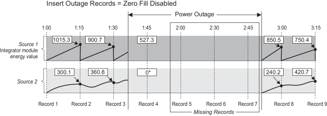
If the Insert Outage Records register is set to yes – zero fill enabled , the records are generated such that each missing parameter in the log has a value of zero. If the Data Recorder module is configured to record any energy values (Integrator module Result output registers), the first missed data record will contain the energy values at the time the power was interrupted. This is done to ensure that the energy values are stored in the appropriate time interval. Refer to the following diagram.
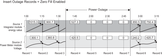
Zero Fill Enabled considerations
NOTE: For all devices, the Insert Outage Records function does not work if the Data Recorder Module’s Source inputs are linked to modules that are triggered in high speed or modules that are triggered asynchronously (i.e., without a consistent interval.)
| Device | Consideration |
|---|---|
| ION8650 | If the Insert Outage Records register is set to yes - zero fill enabled, the LogMode register must be set to high speed continuous or else the module will remain offline. |
| PM8000 series |
You cannot configure the module in such a way that the Insert Outage Records register is set to yes - zero fill enabled AND the Buffer Depth register is set to less than the Log Depth. In order to use yes - zero fill enabled option, make sure that the Buffer Depth is set to equal to or greater than the Log Depth. |
Insert Outage Records = Yes – Zero Fill Disabled
If the Insert Outage Records register is set to yes – zero fill disabled , then the Data Recorder module will not generate any missing records other than the energy value data record mentioned previously. Refer to the diagram below.
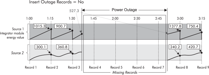
Insert Outage Records = No
If the Insert Outage Records register is set to no, then no missing records are generated. This implies that any energy value accumulated at the time the power was interrupted is carried over to the first interval that is logged after the power resumes. Refer to the diagram below.
Pre-trigger Records and Post-trigger Records: detailed operation
Pre-trigger Records and Post-trigger Records setup registers are set to zero by default.
To capture a number of adjacent data log records that exist immediately before or immediately after a triggered recording, set Pre-trigger Records or Post-trigger Records, respectively.
Capturing pre-trigger and post-trigger data logs is useful in high-speed data recording applications such as power quality event monitoring. The data log set for each triggered recording is equal to the sum of Pre-trigger Records + Post-trigger Records + 1 (where 1 is the actual record when the triggered recording occurred).
For example, if Pre-trigger Records is set to 10 and Post-trigger Records is set to 5, the number of records for each data log set would be 16:
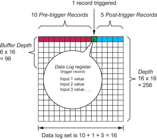
If Pre-trigger Records or Post-trigger Records are set to a non-zero value, both Buffer Depth and Depth setup registers must be set to a positive integer multiple of the data log set.
High-speed ION modules update once every half-cycle. Use the system frequency to calculate the number of records needed to capture 1 second of data:
- For 60 Hz, total number of records per second = 60 cycles/second x 2 half-cycles = 120
- For 50 Hz, total number of records per second = 50 cycles/second x 2 half-cycles = 100
Timestamp mode: detailed operation
Rounding is typically used for reports, or to normalize time with systems that do not have the same time resolution as the device reporting the time.
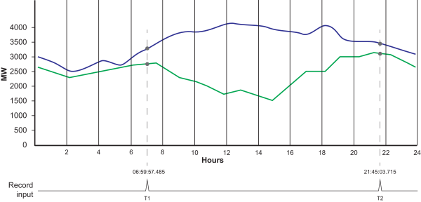
For example, if Timestamp Mode is set to:
- record pulse, the record time for the two triggered recordings (T1 and T2) would be 06:59:57.485 and 21:45:03.715
- round to nearest second, the record time for the two triggered recordings (T1 and T2) would be 06:59:57.000 and 21:45:04.000
- round to nearest minute, the record time for the two triggered recordings (T1 and T2) would be 07:00:00.000 and 21:45:00.000