Differentiator Module
The Differentiator Module takes the simple derivative of a source that changes over time by calculating the rate of change of the source’s value over a defined time interval.
Module icon
![]()
Overview
The rate of change (dx/dt) is calculated using the current and previous values of the Source input and the time difference between those input values. The Result output register contains the value for dx/dt, and is an approximation of the slope of the source graph at those points. The equation below represents the module’s operation.

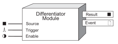
The Differentiator Module can be used in a framework to track the rate of change of frequency, voltage, power or THD and detect any deviation in a normal trend. Detecting subtle changes in your system can help identify issues in your system as they develop, before they create downtime.
NOTE: The registers and settings available in this module depend on the device or node you are configuring, as well as its firmware and template versions. Not all registers or settings are available on all devices or the Virtual Processor, and labels may vary.
Inputs
 Source
This is the source for which you want to evaluate the rate of change. It is typically linked to a numeric output of a high-speed module, such as Frequency or one of the voltage outputs from the HS (high-speed) Power Meter module.
 Trigger
The Trigger input determines the calculation time period (dt) by taking the time difference between the last two pulses. This input is typically linked to an ION module that pulses at regular intervals, such as a Periodic Timer module. If the Trigger input is not linked, it pulses at the same update rate as the source that is connected to the Source input. The update rate for standard modules is once per second. For high-speed modules, the update rate is once every half cycle.
 Enable
This input enables or disables the module. If this input is unlinked, the module is enabled by default.
Setup registers
Differentiator modules have no setup registers.
Output registers
 Result
This numeric register contains the rate of change (dx/dt) of the Source input over the last calculation period, in Source units per second.
 Event
Event
All events are recorded in the Event register.
Possible events and their associated priority numbers are:
| Event priority group | Priority | Description |
|---|---|---|
| Setup change | 10 | Input links or labels have changed. |
The Event output register stores the following information for each ION event: time stamp, priority, cause, effect, and any values or conditions associated with the cause and effect.
Detailed module operation
The Differentiator module can be used to continuously monitor a changing source for rapid or subtle changes in value over the defined calculation time period (dt). The calculation time period (dt) is controlled by the module connected to the Trigger input. Determining an appropriate value for dt depends on the particular application for this module.
To define, detect and trigger an alarm condition based on the value at the Result output register, you can link the Differentiator module’s Result output to a Setpoint or Relative Setpoint module. The Setpoint or Relative Setpoint module’s outputs can then be used to perform control actions, send an alert or initiate data recording.
Setting the appropriate calculation time period (dt) is key to capturing deviations to normal trends for the Source input. Depending on the normal waveform profile of a given source input, the Differentiator module can be used to detect rapid or slow changes to the source input’s rate of change.
For example, the following diagram shows how to connect a Differentiator module to monitor the rate of change in system frequency.

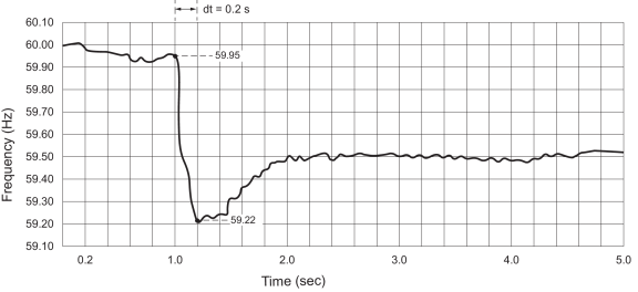
The High-Speed Power Meter module updates once every half cycle. Setting the Periodic Timer module’s Period to 0.2 seconds allows the Differentiator module to detect a dx/dt value of -3.65 Hz per second ((59.22 - 59.95) Hz / 0.2 s), as shown in the graph below.
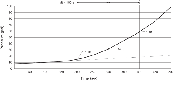
The Differentiator module can also be used to monitor rapid changes to an input that normally has a constant dx/dt slope. In the following example, the dashed line represents pressure being increased at a steady rate of 0.03 psi per second. However, between the 200 and 300 second mark, the Differentiator module’s dx/dt value has increased to 0.17 psi per second. To detect and initiate an action based on this behavior, you can configure a Setpoint module to trigger when dx/dt has increased, for example, to 0.06 psi per second or 200% above the normal value.
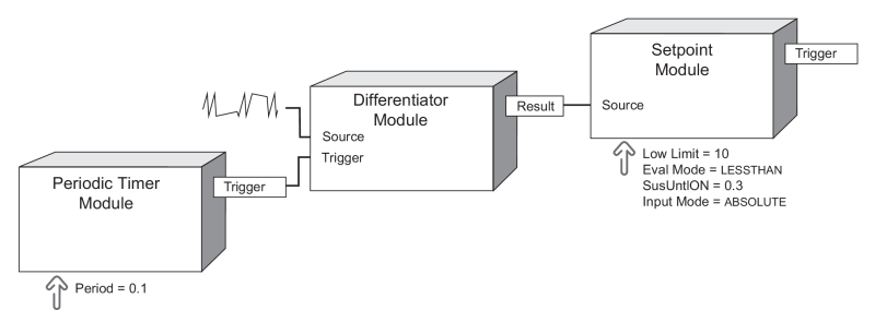
To monitor an input whose values normally change rapidly over time (for example, a sawtooth waveform), the Differentiator module can be used to detect when the slope of the curve has decreased below a certain value. In the following example, one complete cycle of the sawtooth waveform period lasts 0.5 seconds. The waveform has a positive slope of 19 volts per second, and a negative slope of -75 volts per second.
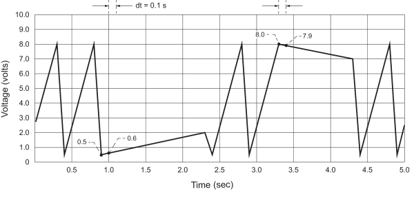
Setting the Periodic Timer module’s Period to 0.1 seconds allows the Differentiator module to detect a low dx/dt value of 1 volt per second between 0.9 and 1.0 seconds, continuing until the 2.3 second mark. A dx/dt value of -1.0 volts per second is detected between 3.3 and 3.4 seconds, continuing until the 4.3 second mark. You can use a Setpoint module to trigger on these values.
Responses to special conditions
The following table summarizes how the module behaves under different conditions:
| Condition | Response of output registers |
|---|---|
| If the Source input value is Not Available. | The Result value is Not Available. |
| After the module is relinked. | The module restarts and updates the Result value after the changes are saved. |
| When the device is restarted or power-cycled. | The module restarts and updates the Result value after power is restored. |