Digital Input Module
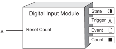
The Digital Input Module detects input signals on a device’s digital input port.
Module icon
![]()
Overview
Digital inputs are typically used in applications such as non-critical status monitoring or pulse counting.
 warning
unintended operation
Do not use this device for critical control or protection applications where human or equipment safety relies on the operation of the control circuit.
Failure to follow these instructions can result in death, serious injury, or equipment damage.

NOTE: The registers and settings available in this module depend on the device or node you are configuring, as well as its firmware and template versions. Not all registers or settings are available on all devices or the Virtual Processor, and labels may vary.
Inputs
 Reset Count
When this input is pulsed, the Count output is reset to zero.
Setup registers
The setup registers define how the Digital Input Module interprets the external signal.
 Input Mode
This register determines how the module processes the signal appearing at the device’s digital input port.
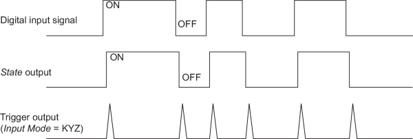
- Select kyz to detect transition pulses (i.e., when the signal changes from ON-to-OFF or OFF-to-ON).
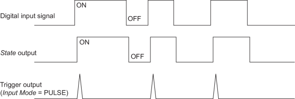
- Select pulse to detect complete pulses.
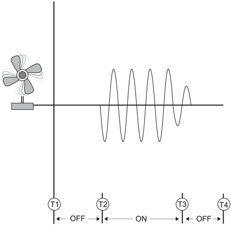
- Select a/c to detect analog signals (where the ON condition is based on the presence of an AC signal with a frequency range of 5 to 210 Hz).
- Select irig-b to detect GPS IRIG-B signals for time synchronization.
 EvLog Mode (event
log mode)
This register specifies if changes in the State output register are recorded as events in the Event output register. If you select log on, these events are logged in the Event output register. If you select log off, these events are not logged.
NOTE: Setup register changes are always logged in the Event output register.
 Event Priority
This numeric bounded register allows you to assign a priority level to changes in the State output register. To record State changes in the Event Log, the Event Priority register value must be greater than the value set in the Event Log Controller module’s Cutoff register. If Event Priority is set to zero (0), State changes will not be logged.
NOTE: Events associated with changes to the module’s State output are recorded only if the EvLog Mode register is set to log on. If EvLog Mode is set to log off, these events will not be recorded, regardless of priority.
 Polarity
This register specifies whether the signal from hardware is inverted (inverting) or not (non-inverting). This setup register is ignored when Input Mode is set to a/c.
 Debounce
This numeric bounded register allows you to compensate for mechanical contact bounce by defining (in seconds) how long the external signal must remain in a certain state to be considered a valid state change. This setup register is ignored when Input Mode is set to a/c.
NOTE: Specifying a debounce time of less than 1 second will cause the Digital Input module, and all ION modules linked to it, to update at 1 cycle intervals. Specifying a debounce time of 1 second or longer changes the update rate to once per second.
 Port
Port
This register defines which hardware port on the ION device is associated with the Digital Input module. Refer to your device’s documentation for a list of available ports.
 Enable
This register specifies whether the module is enabled or disabled. If set to disabled, the Digital Input module does not function.
 Alarm Trigger Mode
This register specifies the behavior of the digital input alarm:
- alarm on on: the associated digital input alarm is active when the digital input State is on.
- alarm off off: the associated digital input alarm is active when the digital output State is off.
Output registers
 State
State
This Boolean register contains the present debounced state of the input.
 Trigger
If the Input Mode setup register is set to pulse, the Trigger output register generates a pulse for each complete pulse detected (i.e., each time the hardware changes to the baseline state). If Input Mode is set to kyz, a pulse is generated each time the signal changes state (from ON-to-OFF or from OFF-to-ON). If Input Mode is set to a/c, this register generates a pulse each time an A/C signal is applied or removed.
 Count
Count
This register contains the number of times the Trigger output register has pulsed since the Reset Count input register was pulsed.
 Event
Event
The Event register records all events produced by the Digital Input Module.
The following table shows possible events and their associated priority numbers:
| Event priority group | Priority | Description |
|---|---|---|
| Reset | 5 | Reset Count has pulsed. |
| Setup Change | 10 | Input links, setup registers or labels have changed. |
| I/O State Change | 1 - 255 | Priority set by Event Priority. Input transaction logged.* |
| Failure | 255 | Frequency of digital input device too high; input device shut down. |
| * These events are only recorded if the EvLog Mode setup register is set to log on and the Event Priority register is set to a value greater than the Event Log Controller module’s Cutoff register. | ||
The Event output register stores the following information for each ION event: time stamp, event priority, event's cause, event's effect, and conditions associated with the event's cause and effect.
Responses to special conditions
The following table summarizes how the Digital Input module behaves under different conditions.
| Condition | Response of output registers |
|---|---|
| When the device is started or powered-up (either the first time or after a shut-down) | The State output matches the state of the hardware port if the Input Mode is set to kyz or pulse. The State output will be OFF if the Input Mode is set to a/c. |
Detailed module operation
Specifying a Debounce Time
Debounce is the time delay you program in the module so that intermediate noise states (e.g., from a switch operation) are ignored. The value you set for the Debounce setup register depends on the type of signal or input device you are monitoring and the meter you are configuring. For solid state dry contacts, 0 to 5 ms is typical. For mechanical dry contacts, 1 to 80 ms is typical.
NOTE: Some input devices may already have a built-in debounce time (sometimes referred to as a Turn On or Turn Off time). Refer to the input device documentation for information.
Pulse Mode
If you set Input Mode to pulse, a pulse is generated at the Trigger output when the State output changes from OFF-to-ON. No pulse is generated when State changes from ON-to-OFF.

NOTE: To trigger ON-to-OFF transitions in pulse mode, set the Polarity register to inverting.
KYZ Mode
If you set Input Mode to kyz, a pulse is generated at the Trigger output for each change of state transition, i.e. from OFF-to-ON and from ON-to-OFF transitions.

A/C Mode
If you set Input Mode to a/c, the digital input port is configured to detect the presence of an A/C waveform. The next illustration shows how a digital input can be used to monitor the operation of a fan.
NOTE: The frequency detection range varies by device; refer to your device’s documentation for specifications.
When the fan turns on (T2), a pulse is generated on the Trigger output register and the State output register changes to on.
When the fan turns off (T3), the State output register changes to off and another pulse is generated on the Trigger output.

Setting the EvLog Mode
For status or equipment monitoring applications, the EvLog Mode setup register is typically set to log on, so events associated with changes to the State output are recorded. For energy pulsing applications, this setup register is typically set to log off.