Digital Output Module
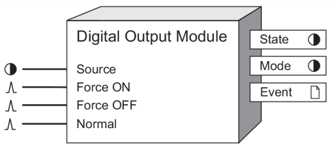
The Digital Output Module acts as an intermediary between another module in the device and a hardware port.
Module icon
![]()
Overview
The Digital Output Module takes a Boolean input and sends it out a hardware channel as a constant level or a pulse. This provides the ability to signal and control external digital devices (such as relays) from the meter.
 warning
HAZARD OF UNEXPECTED DIGITAL OUTPUT STATE CHANGE
Do not use ION meters for critical control or protection applications where human or equipment safety relies on the operation of the control circuit.
| ● | An unexpected change of state of the digital outputs can result when the supply power to the meter is interrupted or after a meter firmware upgrade. |
| ● | Be sure that you are familiar with the warnings at the beginning of this document, as well as those presented in your meter’s technical documentation. |
Failure to follow these instructions can result in death, serious injury, or equipment damage.

NOTE: The registers and settings available in this module depend on the device or node you are configuring, as well as its firmware and template versions. Not all registers or settings are available on all devices or the Virtual Processor, and labels may vary.
Inputs
At least one of these inputs must be linked. Read the descriptions below to select the input appropriate for your application. Refer to “Detailed Module Operation” for more information.
 Source
When linked, the Boolean value appearing at the input is sent to the hardware port specified by the Port setup register. If you leave this input unlinked, the hardware port is controlled only by the Force ON and Force OFF inputs.
 Force ON
When pulsed, this input forces the hardware port on, regardless of the Source input state, and the Force ON and Force OFF inputs control the hardware port. The hardware port specified in the Port setup register is pulsed on for the amount of time entered in the PulseWidth setup register.
NOTE: If the PulseWidth setup register is zero, the hardware port is continuously on until a pulse is received on the Force OFF input.
 Force OFF
When pulsed, this input forces the specified hardware port off, regardless of the Source input state, and the Force ON and Force OFF inputs control the hardware port. The Force OFF input is only valid if the PulseWidth setup register is set to zero, and will be ignored if the PulseWidth setup register is non-zero.
 Normal
If the hardware port is being controlled by the Force ON input, pulsing this input changes hardware port control to the Source input. The Normal register is only valid if the PulseWidth setup register is set to zero, and is ignored if the PulseWidth setup register is non-zero.
Setup registers
The setup registers of the Digital Output Module define what kind of output the module produces and on which hardware port.
 EvLog Mode (event log mode)
This register determines whether hardware port state changes are logged in the Event output register. If you select Log On, these events are logged; if you select Log Off, these events are not included in the Event register. The events associated with linking the module and changing setup registers are always logged regardless of the EvLog Mode register setting.
 Polarity
This register controls whether the module inverts the input before sending it to the hardware port (inverting) or not (non-inverting).
 PulseWidth
This register specifies the on time of the output pulse sent to the hardware port (how many seconds the digital output is on). If this register is set to zero, the hardware port is set to continuously on.
 Port
Port
This register determines to which hardware port the pulse or output signal is sent. Some meters have internal mechanical relays. Refer to your meter documentation for a list of available ports.
notice
HAZARD OF MISAPPLICATION (MISUSE)
Because mechanical relays have limited lifetimes, mechanical KYZ relays are typically not suitable for energy pulsing applications. For energy pulsing applications, consider using Form A outputs in KYZ mode.
Failure to follow these instructions can result in equipment damage.
Output registers
 State
State
This register reflects the present status of the hardware port. Refer to “Detailed Module Operation” for more information.
 Mode
Mode
This Boolean register indicates which input controls the hardware port. If the Force ON and Force OFF inputs control the hardware port, the Mode register is on. If the Source input controls the hardware port, the Mode register is off.
 Event
Event
All events produced by a Digital Output Module are written into this register.
Possible events and their associated priority numbers are:
| Parameter | Values | Description |
|---|---|---|
| Setup Change | 10 | Input links, setup registers or labels have changed. |
| I/O State Change* | 20 | Output forced on, forced off or forced normal; output transaction has occurred. |
| * These events are only recorded if the EvLog Mode setup register is set to LOG ON.. | ||
The Event output register stores the following information for each ION event: time stamp, priority, cause, effect, and any values or conditions associated with the cause and effect.
Detailed module operation
A primary function of the Digital Output Module is to physically control the operation of a relay or device connected to the meter’s digital output port.
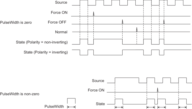
This figure illustrates the basic operation of a Digital Output Module, showing the operation of all the possible inputs when the PulseWidth is equal to zero and when the PulseWidth is non-zero.

NOTE: The pulse width is dependent on the operate period of the Digital Output Module. For example, if a Digital Output Module is operating at 1-second intervals, the pulse width will be a multiple of 1 s, rounded up from the value set in the PulseWidth register.
When configuring the Digital Output Module, consider the characteristics of your external relay or device, such as whether it is normally closed or open (for your meter’s digital output characteristics, refer to the meter’s Installation Guide). You can use the Polarity setup register to ensure the State correctly reflects the actual state of the external relay or device, or you can modify the State register’s on/off labels.
The following table lists the combinations of Digital Output inputs and Polarity settings, and the result sent to the hardware port and shown in the State output register:
| Relay type | Input to Digital Output module | Polarity | State output* |
|---|---|---|---|
| Normally Open | ON | Non-Inverting | ON |
| Normally Open | OFF | Non-Inverting | OFF |
| Normally Closed | ON | Inverting | ON |
| Normally Closed | OFF | Inverting | OFF |
| * The ON/OFF State output register labels are user-configurable. | |||
Responses to special conditions
The following table summarizes how the Digital Output Module behaves under different conditions.
| Condition | Response of output registers |
|---|---|
| If the Source input is not available | The output registers retain the state they held when the Source input was available. The module still responds to Force On and Force Off pulses. Note: If the Port setup register is set to notused, output registers will be not available. |
| When the device is started or powered-up (either the first time, or after a shut-down) | The output registers are off (0). All force conditions (i.e. Force On or Force Off) are discarded. Note: If the Port setup register is set to notused, output registers will be not available. |