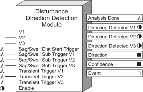
Disturbance Direction Detection Module
The purpose of this module is to determine the direction of a disturbance, relative to the meter.
Module icon
![]()
Overview
Analyzing disturbance direction detection information from multiple meters in a power monitoring system enables the location of the cause of the disturbance to be determined more quickly and accurately.
When a disturbance pulse is received, the module runs the Disturbance Direction Detection algorithm. The algorithm analyzes the input data to determine the direction of a disturbance. It also assigns a confidence score to the results of its analysis. The direction information and the confidence level are output as an event, recorded in the Event Log. The event log record has the same timestamp as the disturbance that triggered the Disturbance Direction Detection Module, even though the results of the algorithm may appear in the event log after the disturbance is over.

NOTE: The registers and settings available in this module depend on the device or node you are configuring, as well as its firmware and template versions. Not all registers or settings are available on all devices or the Virtual Processor, and labels may vary.
Inputs
 V1, V2, V3
These inputs are linked to the outputs of the Data Acquisition module. These links cannot be changed.
 Sag/Swell Dist (Disturbance) Start Trigger
This input register is of the pulse class and is intended to be connected to the Sag/ Swell module DistStart output register. A pulse received on this register indicates to the module that a Sag/Swell has occurred and activates the disturbance direction detection algorithm to determine the direction of the disturbance. While the algorithm is running, any further pulse to this input is ignored.
 Sag/Swell Sub
Trigger V1, Sag/Swell Sub Trigger V2, Sag/Swell Sub Trigger V3
These input registers are of the pulse class and are intended to be connected to the Sag/Swell module’s SubV1Trig, SubV2Trig and SubV3Trig outputs, respectively. A pulse on one of these inputs, in conjunction with a pulse on the Sag/ Swell Dist Start Trigger, indicates to the module on which phase a sag/swell disturbance alarm has occurred. Any pulses that are not received in conjunction with a pulse on the Sag/Swell Dist Start Trigger are ignored.
 Transient Trigger
V1, Transient Trigger V2, Transient Trigger V3
These input registers are of the pulse class and are intended to be connected to the Transient module’s TranV1Trig, TranV2Trig and TranV3Trig outputs, respectively. A pulse on one of these inputs indicates to the module on which phase a transient disturbance alarm has occurred and activates the disturbance direction detection algorithm to determine the direction of the disturbance. While the algorithm is running, any further pulses to these inputs are ignored.
If a sag/swell and a transient alarm are triggered simultaneously, the module analyzes the disturbance as a sag/swell.
 Enable
This input enables or disables the module’s operation. When linked to another module’s Boolean output, it turns the module on and off. If the module is off, it ignores any disturbance pulses it receives and the output registers display not available or, in the case of the Analysis Done register, zero. This input is optional—if left unlinked, the module is enabled by default.
Setup registers
 EvPriority
This register allows you to set a custom priority level for certain events generated by the module and written to the Event output register. See the Event output register description for details.
Output registers
 Analysis Done
This output is pulsed when the disturbance direction detection algorithm has finished its analysis and new disturbance direction information is available in the output registers.
 Direction Detected V1, Direction
Detected V2, Direction Detected V3
These Boolean output registers are updated when the disturbance direction detection algorithm is complete. A value of true (1) indicates that a disturbance and its direction were detected on the channel. A value of false (0) indicates that no disturbance or direction were detected on the channel.
 Direction
This register’s value is updated when a disturbance direction is detected. A value of -1 indicates the disturbance is upstream, a value of 1 indicates a disturbance is downstream, and a value of 0 indicates the disturbance direction is indeterminate.
 Confidence
This register expresses, as a numeric value, the confidence score of the determined direction of the disturbance. The output value is a score from 0 to 100, determined using a points system, that indicates the level of confidence in the direction determined by the algorithm. The following table shows how the confidence score is translated into the confidence written to the Event output register:
| Score | Level |
|---|---|
| 0–9 | Indeterminate |
| 10–29 | Low |
| 30–69 | Medium |
| 70–100 | High |
 Event
Event
All events produced by the module are written into this register.
Possible events and their associated priority numbers are shown in the table below:
| Event priority group | Priority | Description |
|---|---|---|
| Setup register change | 10 | Input Links, setup registers or labels have been changed. |
| DDD Event | * | Disturbance Direction detected. |
| * The priority of these events are set in the EvPriority setup register. | ||
The Event output register stores the following information for each ION event: time stamp, priority, cause, effect, and any values or conditions associated with the cause and effect.
Responses to special conditions
The following table summarizes how the module behaves under different conditions.
| Condition | Response of output registers |
|---|---|
| If the Enable input is off | The output registers are not available or zero, depending on the register. |