Harmonics Analyzer Module
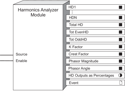
The Harmonics Analyzer Module provides detailed harmonics calculations for a voltage or current input on the device.
Module icon
![]()
Overview
This information is valuable for power quality analysis, selecting properly rated transformers, and fault detection. The Harmonics Analyzer Module can have output register values with the following information:
- individual harmonic distortion
- total harmonic distortion
- total odd harmonic distortion
- total even harmonic distortion
- K-Factor (for current inputs)
- Crest-Factor (for current inputs)
- Phasor Magnitude
- Phasor Angle
- Outputs as Percentages

NOTE: The registers and settings available in this module depend on the device or node you are configuring, as well as its firmware and template versions. Not all registers or settings are available on all devices or the Virtual Processor, and labels may vary.
Inputs
 Enable
The Enable input is factory-linked and cannot be altered.
The Source input of Harmonics Analyzer Modules is fixed. It receives data either from the voltage or current.
Setup registers
 Harmonics Display Mode
This register specifies how the individual harmonic distortion output values are displayed. Choices include:
- Engineering units
- Percentages of the fundamental, nominal (Factory module) or RMS.
 THD Display Mode
This register specifies how the total harmonic distortion output values are displayed. Choices include percentages of the fundamental, nominal (Factory module) or RMS.
Output registers
 HD1...HDn (harmonic distortion 1…n)
These registers contain the harmonic distortion of the input for each individual harmonic.
 Total HD (total harmonic distortion)
This register contains the total harmonic distortion of the input. An FFT is performed on the sample waveform to determine the harmonic components of the signals. They are then used in the following formula:
 | k | the highest harmonic order number | |
| n | the harmonic order number | ||
| f1 | the magnitude of the fundamental | ||
| fn | the magnitude of the nth harmonic | ||
 Tot EvenHD (total
even harmonics distortion)
This register contains the total even harmonic distortion of the input.
 Tot OddHD (total odd harmonics distortion)
This register contains the total odd harmonic distortion of the input.
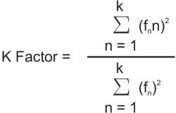
 K Factor
This register contains the K-Factor of the input signal. It is available only for current inputs. An FFT is performed on the sample current waveform to determine the harmonic components of the signals. They are then used in the following formula:
 | k | the highest harmonic order number | |
| n | the harmonic order number | ||
| fn | the magnitude of the nth harmonic | ||
 Crest Factor
This register contains the Crest Factor of the input signal. It is available only for current inputs.
 Phasor Magnitude
This register contains the magnitude, in engineering units, of the fundamental component. It is available for current and voltage inputs.
 Phasor Angle
This register contains the phase, in degrees, of the fundamental component, relative to V1. It is available for current and voltage inputs.
 HD Outputs as Percentages
This Boolean register indicates if individual harmonic distortion values are being displayed as percentages. On = yes and Off = no.
 Event
Event
Any events produced by the Harmonics Analyzer module are recorded in the Event register.
Possible events and their associated priority numbers are shown in the following table:
| Event priority group | Priority | Description |
|---|---|---|
| Setup Change | 10 | Input links, setup registers or labels have changed. |
The Event output register stores the following information for each ION event: time stamp, event priority, event's cause, event's effect, and conditions associated with the event's cause and effect.
Responses to special conditions
The following table summarizes how the Harmonics Analyzer module behaves under different conditions.
| Condition | Response of output registers |
|---|---|
| If the Source input is not available | All output registers are not available. |
| If the Enable input is off | All output registers are not available. |
| When the device is started or powered-up (either the first time, or after a shut-down) | All output registers are not available. |
| If the RMS value or fundamental component is zero | All harmonics for that channel is zero*. |
| * Applies to V1, V2, V3, I1, I2, I3. For I4, all harmonics will be zero only if the RMS value is zero. If the fundamental component is zero, the harmonics will be N/A. | |
Effect of meter configuration on harmonics
The Volts Mode setting of the devices require PT and CT configurations that prevent the calculation of certain harmonics. The following table outlines these considerations:.
| Volts Mode setting | Affected harmonics modules |
|---|---|
| Delta | All outputs of V2 and I4 are not available. |
| 3W-WYE | All outputs of V2 are not available. |
| Single Phase | All outputs of V3 and I3 are not available. |