Harmonics Measurement Module
This module measures the magnitude and phase of harmonic frequencies.
Module icon
![]()
Overview
Alternatively, the Harmonics Measurement module can be set to provide the magnitude of inter-harmonic frequencies.

Total Harmonic Distortion (THD), Total Even Harmonic Distortion (TEHD), and Total Odd Harmonic Distortion (TOHD) are always calculated; THDcap and THDind are calculated if you are measuring voltage.
NOTE: The registers and settings available in this module depend on the device or node you are configuring, as well as its firmware and template versions. Not all registers or settings are available on all devices or the Virtual Processor, and labels may vary.
Inputs
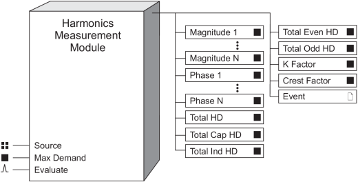
 Source
The Source can only be linked to the FFT output of an FFT module (such as V1, V23 or I3 FFT).
 Max Demand
If this input is linked, the module can use this value to calculate its THD, TEHD, and TOHD percentages based on this input (i.e. total demand distortion). Otherwise, it calculates them based on the magnitude of the fundamental. Linking this input is optional.
NOTE: This input is only used if the Display Mode is set to magnitude outputs displayed as percentages or the THD Display Mode is set to percentages.
 Evaluate
A pulse at this input triggers the module to perform its statistical evaluation, and update its output registers. The phase, THDcap, and THDind outputs are not available when this input is active. If this input is not linked, the module updates its outputs as it did previously. This input cannot be linked when Aggregate Mode is set to 4-30 150/180 Cycle mode or 4-30 10 Minute mode.
This input is intended to be pulsed at either 15 second or 10 minute intervals.
Setup registers
 Measure Type
This setup register specifies whether the module is performing a harmonics or inter-harmonics measurement.
 Aggregate Mode (or Aggregation Method)
This setup register specifies the aggregation interval or aggregation type, depending on whether or not the Evaluate input is linked.
NOTE: If the Evaluate input is unlinked, the module defaults to the 4-30 150/180 cycle.
If the Evaluate input is linked, the aggregation period is automatically set to be the interval between Evaluate input pulses. Select either:
- Maximums: maximum harmonic values for the period.
- Aggregation: average harmonic values for the period.
If the Evaluate input is not linked, select the desired aggregation period:
- 4-30 150/180 Cycle: aggregate over the interval defined by the 4-30 150/180 cycle.
- 4-30 10 Minute: aggregate over the interval defined by the 4-30 10 minute period.
 Display Mode (or
Calculation Type)
This setup register specifies how the individual magnitude output values are calculated by the module and the format of the output values. Choices include:
- Engineering units: the harmonic magnitudes are provided in the units of volts or amps (based on the Source input).
- Percentages: the harmonic magnitudes are expressed as a percentage of Max Demand (maximum demand) if this register is linked, otherwise the harmonic magnitudes are expressed as a percentage of the fundamental harmonic (H1).
- Percent fundamental: the harmonic magnitudes are expressed as a percentage of the fundamental harmonic (H1).
- Percent RMS: the harmonic magnitudes are expressed as a percentage of the sum of all the harmonic components including the fundamental harmonic.
- Percent nominal: the harmonic magnitudes are expressed as a percentage of the nominal voltage or current value as defined in the Factory module.
 THD Display Mode
This setup register specifies how the total harmonics output values (THD, TOHD and TEHD) are calculated by the module. Choices include:
- Percentages: the harmonic magnitudes are expressed as a percentage of Max Demand (maximum demand) if this register is linked, otherwise the harmonic magnitudes are expressed as a percentage of the fundamental harmonic (H1).
- Percent fundamental: the harmonic magnitudes are expressed as a percentage of the fundamental harmonic (H1).
- Percent RMS: the harmonic magnitudes are expressed as a percentage of the sum of all the harmonic components including the fundamental harmonic.
- Percent nominal: the harmonic magnitudes are expressed as a percentage of the nominal voltage or current value as defined in the Factory module.
Output registers
 Magnitude 1 to Magnitude N
These output registers provide the magnitude of the harmonic or inter-harmonic. When the module is operating in inter-harmonics mode, magnitude identifies the signal component between the (n-1) and (nth) harmonic; for example, Magnitude 2 specifies the inter-harmonic band between the fundamental and the 2nd harmonic.
 Phase 1 to Phase N
These output registers provide the phase angle of each harmonic; the angles are relative to the angle of the fundamental of V1.
 Total HD (150/180
Cycles)
The phase signal's total harmonic distortion.
 Total Cap HD
The phase signal's total capacitive harmonic distortion. This measurement is not available when the Measure Type is set to evaluate inter-harmonics or connected to a Current FFT module.
 Total Ind HD
The phase signal's total inductive harmonic distortion. This measurement is not available when the Measure Type is set to evaluate inter-harmonics or connected to a Current FFT module.
 Total Even HD (total even harmonics
distortion)
This register contains the total even harmonic distortion of the input.
 Total Odd HD (total odd harmonics
distortion)
This register contains the total odd harmonic distortion of the input.
 K Factor
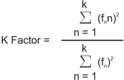
This register contains the K-Factor of the input signal. It is available only for current inputs. An FFT is performed on the sample current waveform to determine the harmonic components of the signals. They are then used in the following formula:
 | k | the highest harmonic order number | |
| n | the harmonic order number | ||
| fn | the magnitude of the nth harmonic | ||
 Crest Factor
This register contains the Crest Factor of the input signal.
 Event
Event
All events produced by the module are written into this register.
Possible events and their associated priority numbers are shown in the following table:
| Event priority group | Priority | Description |
|---|---|---|
| Setup Change | 10 | Input links, setup registers or labels have been changed. |
The Event output register stores the following information for each ION event: time stamp, priority, cause, effect, and any values or conditions associated with the cause and effect.
Detailed module operation
The module performs harmonic analysis as specified in IEC 61000-4-30 (IEC 61000-4-7) harmonics and interharmonics if configured with 4-30 settings.
NOTE: Magnitude and phase outputs are accessible on some devices’ displays. Refer to your device documentation for more information.