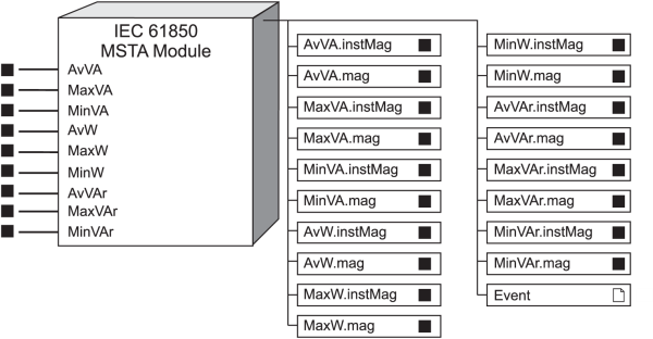
IEC 61850 MSTA Module
The IEC 61850 MSTA module represents the Metering Statistics (MSTA) Logical Node in IEC 61850 protocol.
Module icon
![]()
Overview
It maps the appropriate ION values to their IEC 61850 counterparts. The MSTA Logical Node provides metering statistics, such as average, minimum and maximum values. Only one instance of this module can exist. Because this module is specific to supporting the IEC 61580 protocol, it can be deleted if IEC 61850 is not required.
NOTE: This module is configured as part of the meter’s implementation of the IEC 61850 protocol. Manual creation and configuration of this module, or modification of an existing module, is an advanced feature that should only be undertaken by personnel with a thorough understanding of ION and IEC 61850 protocols, and the system in which the meter is installed.
For more information about IEC 61850, please refer to the IEC 61850 and ION Technology protocol document.

NOTE: The registers and settings available in this module depend on the device or node you are configuring, as well as its firmware and template versions. Not all registers or settings are available on all devices or the Virtual Processor, and labels may vary.
Inputs
By default, the MSTA module inputs are linked to the outputs of the related Maximum, Minimum and Sliding Window Demand modules.
NOTE: If input registers are changed, the new inputs must have the same units of measure as the original input.
 AvVA
AvVA
This register is linked to the output register of the kVA tot mean Sliding Window Demand module, which provides the average apparent power value. Units are kVA.
 MaxVA
MaxVA
This register is linked to the output of the kVA tot mx Maximum module, which provides the maximum apparent power value. Units are kVA.
 MinVA
MinVA
This register is linked to the output of the kVA tot mn Minimum module, which provides the minimum apparent power value. Units are kVA.
 AvW
AvW
This register is linked to the output register of the kW tot mean Sliding Window Demand module, which provides the average real power value. Units are kW.
 MaxW
MaxW
This register is linked to the output of the kW tot mx Maximum module, which provides the maximum real power value. Units are kW.
 MinW
MinW
This register is linked to the output of the kW tot mn Minimum module, which provides the minimum real power value. Units are kW.
 AvVAr
AvVAr
This register is linked to the output register of the kVAR tot mean Sliding Window Demand module, which provides the average reactive power value. Units are kVAR.
 MaxVAr
This register is linked to the output of the kVAR tot mx Maximum module, which provides the maximum reactive power value. Units are kVAR.
 MinVAr
This register is linked to the output of the kVAR tot mn Minimum module, which provides the minimum reactive power value. Units are kVAR.
Setup registers
The MSTA module has no setup registers.
Output registers
These registers are formatted and named according to IEC 61850 protocol standards. These registers have the same units as their corresponding inputs.
 AvVA.instMag, AvVA.mag
These registers contain the instantaneous and deadbanded values for the average apparent power, derived from the AvVA input.
 MaxVA.instMag,
MaxVA.mag
These registers contain the instantaneous and deadbanded values for the maximum apparent power, derived from the MaxVA input.
 MinVA.instMag, MinVA.mag
These registers contain the instantaneous and deadbanded values for the minimum apparent power, derived from the MinVA input.
 AvW.instMag, AvW.mag
These registers contain the instantaneous and deadbanded values for the average real power, derived from the AvW input.
 MaxW.instMag,
MaxW.mag
These registers contain the instantaneous and deadbanded values for the maximum real power, derived from the MaxW input.
 MinW.instMag, MinW.mag
These registers contain the instantaneous and deadbanded values for the minimum real power, derived from the MinW input.
 AvVAr.instMag,
AvVar.mag
These registers contain the instantaneous and deadbanded values for the average reactive power, derived from the AvVAr input.
 MaxVAr.instMag, MaxVAr.mag
These registers contain the instantaneous and deadbanded values for the maximum reactive power, derived from the MaxVAr input.
 MinVAr.instMag,
MinVAr.mag
These registers contain the instantaneous and deadbanded values for the minimum reactive power, derived from the MinVAr input.
 Event
Event
Events produced by the module are recorded in the Event register.
Possible events and their associated priority numbers are shown in the following table.
| Event priority group | Priority | Description |
|---|---|---|
| Reset | 5 | A module reset has occurred. |
| Setup Change | 10 | Input links, setup registers or labels have changed. |
| Information | 25 | not available input caused output to go not available. |
The Event output register stores the following information for each ION event: time stamp, priority, cause, effect, and any values or conditions associated with the cause and effect.