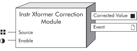
Instr Xformer Correction (ITC) Module
The Instrument Transformer Correction (ITC) Module is a core module that allows you to correct for inaccuracies in the current transformers (CTs) and potential transformers (PTs).
Module icon
![]()
Overview
There is an Instr Xformer Correction Module for each current and voltage input into the meter.
The primary application for instrument transformer correction is to apply correction factors for ratio errors and phase angle errors to instrument transformers. Instrument transformer correction reduces or eliminates the need to replace less accurate transformers in installations where high-accuracy is required.

NOTE: The registers and settings available in this module depend on the device or node you are configuring, as well as its firmware and template versions. Not all registers or settings are available on all devices or the Virtual Processor, and labels may vary.
Inputs
 Source
The Instr Xformer Correction Module takes the value of this input from the Data Acquisition module. This link cannot be changed. For Instr Xformer Correction modules that are correcting current inputs, this source input is I1, I2, I3, I4, or I5. For the Instr Xformer Correction modules that are correcting voltage inputs, this source is V1, V2, V3, or V4.
Setup registers
 Ratio Correction Type
This enumerated register determines what type of modeling is performed to correct the CT or PT ratio. The options are none or piecewise linear. See “Detailed Module Operation” for details.
 Phase Correction Type
This enumerated register determines what type of modeling is performed to correct the phase angle of the CT or PT. The options are none or piecewise linear. See “Detailed Module Operation” for details.
 Ratio Correction Data
This register contains a string of delimited pairs of test points and associated Ratio Correction Factors (RCF) for the CT or PT. The test point is expressed as a percentage of the rated secondary nominal rating. The definition of RCF is:
- RCF = True Ratio/Marked Ratio
- Percent Error = (RCF -1) x100%
Ratio Correction Factor (RCF) is expressed as a decimal value. For validation purposes, the RCF value is deemed out of range if it is greater than 2.0 or less than 0.0. For usage example, see “Sample Ratio Correction Test”.
 Phase Correction Data
This register contains a string of delimited pairs of the test points and associated error for the phase angle of the CT or PT. The test point is expressed as a percentage of the rated secondary nominal rating. The phase angle error is expressed as a real value in minutes.
For validation purposes, a Phase Angle Error value is deemed out of range if it is greater than 600 minutes or less than -600 minutes (which is 10 degrees error). For usage example, see “Sample Phase Angle Test”.
NOTE: Ratio Correction Data and Phase Correction Data are configured independently, so you can have different number of test points for each. However, the maximum number of test data points for each of these registers is 8. Test point location is user-defined.
 Secondary Nominal Rating
This setup register allows you to input the secondary rated nominal current or voltage value depending upon whether the Instr Xformer Correction module is correcting CT or PT. For current inputs, the secondary nominal rating is typically 5A or 1A depending on the CT. For PTs, a secondary nominal voltage rating may range from 63.5 VAC line-to-neutral to 347 VAC line-to-neutral or 600 VAC line-to-line. The default value for current inputs depends upon the framework (5A or 1A); the default value for voltage nominal is 120 VAC.
The allowable range for a CT secondary nominal rating is between 0.001-20 A. The allowable range for a PT secondary nominal rating is between 0.1-1000 VAC.
Output registers
 Corrected Value
The Corrected Value output is factory linked to the Power Meter module and cannot be altered.
 Event
Event
All events produced by an Instr Xformer Correction module are written into this register. The Instr Xformer Correction module considers the following as an event: any changes to the setup registers, input links or labels. These events all have a pre-defined priority of 10.
Detailed module operation
The Instr Xformer Correction module is a core module. There is an Instr Xformer Correction module for each current input – I1, I2, I3 (also I4 and I5, if available) and for each voltage input to the meter – V1, V2, V3 (also V4, if available).
NOTE: The correction affects only the 1-second values in the Power Meter module. No high-speed, harmonics, or waveform values are affected by the correction.
Correction types
You can select the following settings for Ratio Correction Type and Phase Correction Type.
| Setting | Description |
|---|---|
| none | The module does not apply any correction to the source input of the module. |
| piecewise linear | If you select piecewise linear, a secondary nominal value must be entered. The default secondary current nominal value is 5 A. The default secondary voltage nominal value is 120 VAC. Next, you must enter in the Ratio Correction and Phase Angle Test Data. This test data is entered in a string of delimited pairs in a bracket and comma delimited format in sequential descending order. |
For Ratio Correction Test, the string of points is based on the pairing of the secondary input test point and the associated Ratio Correction Factor (RCF). The input test point is assumed to be based on the fundamental (i.e. the 50Hz or 60Hz component) of the input source of the meter. The pair has the following syntax:
{<input test point (%)>, <RCF>}
An example of test data points is shown below:
| Test Point (% nominal) | RCF |
|---|---|
| 100 | 0.998 |
| 50 | 1.000 |
| 25 | 1.001 |
| 10 | 1.003 |
| 1 | 1.008 |
| 0.2 | 1.010 |
The input for this data would be:
{100,0.998},{50,1.0},{25,1.001},{10,1.003},{1,1.008},{0.2,1.010}
For Phase Angle Test data, the string of points is based on the pairing of the input test point and the associated Phase Angle error in minutes. The input test point is assumed to be based on the fundamental (i.e., the 50 Hz or 60 Hz component) of the input source. The pair has the following syntax:
{<input test point (%)>, <minutes>}
For example, a typical test on an instrument transformer may reveal the following results:
| Test Point (% nominal) | Phase Angle Error (Minutes) |
|---|---|
| 100 | 3 |
| 50 | 6 |
| 25 | 10 |
| 10 | 13 |
| 1 | 25 |
| 0.2 | 40 |
The input for this data would be:
{100,3},{50,6},{25,10},{10,13},{1,25},{0.2,40}
NOTE: The figures in the above examples are shown for illustration purposes only. Some meters support test point ranges such as 0.02% to 2500% nominal.
Determining Ratio Correction Factor
Ratio Correction Factor (RCF) is calculated as follows:

Determining Correction Angle
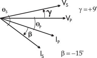
As shown in the example below, if the secondary voltage (Vs) is leading the primary voltage, the correction angle is positive. Enter a positive number. If the secondary current (Is) is lagging the primary current, the correction angle is negative. Enter a negative number.
