Integrator Module
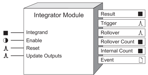
The Integrator module takes the integral of a specified source value (Integrand) over time (Divisor).
Module icon
![]()
Overview
The equation below represents the module's operation.

Once divided, the integrand is added to the previous result of Rn. The update rate of the ION meter determines how often Rn is calculated. The remainder value (the amount left over when the integrand is not an even multiple of the divisor) is stored inside the module to be added into the next integrand. Refer to “Example”.
The most common application of the Integrator module is to calculate energy values, such as:
- Real energy, or kW hours (kWh)
- Reactive energy, or kVAR hours (kVARh)
- Apparent energy, or kVA hours (kVAh)

NOTE: The registers and settings available in this module depend on the device or node you are configuring, as well as its firmware and template versions. Not all registers or settings are available on all devices or the Virtual Processor, and labels may vary.
Inputs
 Integrand
This input is the value which is integrated. It must be linked to a numeric output register of another module.
 Enable
This input enables or disables integration - when disabled, the module stops updating the Result output register. The Integrator module is enabled by default.
NOTE: The Reset input will still function if the module's Enable input is off.
 Reset
Reset
Pulsing this input resets the Result, Rollover Count and Trigger Count output registers to zero. It also resets the remainder value to zero. The Integrator module may be reset even if it is disabled.
 Update Outputs
This pulse register is intended to be pulsed each 15 minutes to allow accurate validation in MV90. It can be set to pulse at any interval.
 Interval Reset
Pulsing this input resets the Result, Rollover Count and Trigger Count registers to zero. The remainder value is carried over into the next interval.
Setup registers
 Divisor
This numeric bounded register specifies the value, in seconds, by which the Integrand is divided before it is added to the Result. For example, to calculate kWh, the Divisor register would be set to 3600.
 Int Mode
The table below describes the modes of integration that may be selected.
| Mode | Description |
|---|---|
| forward | Used for imported energy - only positive integrands are added to the Result output. |
| reverse | Used for exported energy - only negative integrands are added to the Result output. |
| absolute | Used to obtain the absolute values of imported and exported energy - both positive and negative integrands are added to the Result output. |
| net | Used to obtain the difference between the imported and exported energy (a net export of energy is displayed as a negative number). |
 Valu/Pulse
This numeric bounded register defines the value the Result must increase (or decrease) by for a pulse to be generated on the Trigger output. Setting this register to zero disables the feature (no pulses will be output from the Trigger register).
 RollValue
When the Result output register reaches the value specified by the RollValue setup register, the Result output register will rollover (be reset to 0). Setting this register to zero disables the Rollover feature (no rollovers will occur).
Output registers
 Result
This numeric register contains the result of the integration. The Result will rollover (reset to zero) if the value in the Rollvalue setup register is reached.
 Trigger
This register generates a pulse every time the Result output increases or decreases by the value specified in the Valu/Pulse setup register. If the Result increases by double the Valu/Pulse register, two pulses are generated, etc.
NOTE: The Trigger output functions the same in net mode as it does when the absolute mode is used.
 Rollover
This register generates a pulse every time the Result output reaches the value specified in the RollValue setup register.
 Rollover Count
This register increments each time the Rollover output is pulsed.
 Trigger Count
This register increments each time the Trigger output is pulsed.
 Event
Event
Any events produced by the Integrator module are recorded in the Event register.
Possible events and their associated priority numbers are shown in the following table:
| Event priority group | Priority | Description |
|---|---|---|
| Reset | 5 | A module reset has occurred. |
| Setup Change | 10 | Input links, setup registers or labels have changed. |
The Event output register stores the following information for each ION event: time stamp, priority, cause, effect, and any values or conditions associated with the cause and effect.
Responses to special conditions
The following table summarizes how the module behaves under different conditions:
| Condition | Response of output registers |
|---|---|
| Input not available | Integrating stops and the Result output holds the current value. |
| Enable input is off | Integrating stops and the Result output holds the current value. |
| Module is re-linked or setup registers changed | The Result, Rollover Count and Trigger Count outputs go to zero. |
| Meter is started or powered-up | The output registers retain the values they held at shutdown. |
Detailed module operation
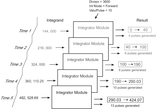
The figure below illustrates the operation of the Integrator module. Typically, the Integrand would be a measurement from one of the output registers of the Power Meter module. Integrating power measurements such as kW provides accumulating energy values in the Result register.

If the value in the Result output register increases by an uneven multiple of the Valu/Pulse, the remainder value is carried over to the next update time.
Example
If Valu/Pulse = 10 and the Result increases by 17, then only 1 pulse will be generated by the Trigger register. The remainder value of 7 is carried over to contribute to the pulse calculation at the next time interval.
If Reset is pulsed, Result, Trigger Count and the remainder value will be set to zero.
If Interval Reset is pulsed, Result and Trigger Count will be set to zero. The remainder value of 7 will be carried over to contribute to the pulse calculation at the next time interval.