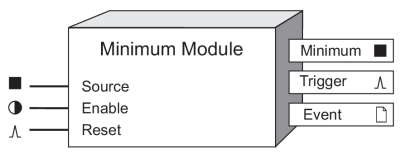
Minimum Module
The Minimum Module records the minimum value reached by a single Numeric Variable. The minimum can be reset and enabled or disabled.
Module icon
![]()
Overview

NOTE: The registers and settings available in this module depend on the device or node you are configuring, as well as its firmware and template versions. Not all registers or settings are available on all devices or the Virtual Processor, and labels may vary.
Inputs
 Source
This input is monitored for a minimum value. It must be a numeric variable register from any other module’s outputs. Linking this input is mandatory. The Minimum Module ignores any source that is not available.
 Enable
This input enables or disables the Minimum Module (by setting it to on or off respectively). When a Minimum Module is disabled, it disregards any new minimum values in the Source input. This input is optional; if you leave it unlinked, the module is enabled by default.
 Reset
Reset
This input resets the Minimum Module, setting the Minimum output register to not available. The module can be reset even if it is disabled. This input must be a pulse register from any other module’s outputs. This input is optional; if you leave it unlinked, it will by default never receive a pulse.
NOTE: The Reset input will still function if the module’s Enable input is off
Setup registers
Minimum modules have no setup registers.
Output registers
 Minimum
This numeric variable register contains the minimum value attained by the Source input, since the last reset.
 Trigger
Each time a new minimum value occurs, the Trigger output register generates a pulse.
 Event
Event
All events are recorded in the Event register.
Possible events and their associated priority numbers are:
| Event priority group | Priority | Description |
|---|---|---|
| Reset | 5 | A module reset has occurred. |
| Setup Change | 10 | Input links, setup registers or labels have changed. |
The Event output register stores the following information for each ION event: time stamp, priority, cause, effect, and any values or conditions associated with the cause and effect.
Responses to special conditions
The following table summarizes how the module behaves under different conditions.
| Condition | Response of output registers |
|---|---|
| If the Source input is not available | The Minimum output retains the value it held when the Source input was available. |
| If the Enable input is off | The Minimum output retains the value it held when the Source input was available. |
| After the module is re-linked or its setup registers are changed | The Minimum register is not available. |
| When the module is started or powered-up (either the first time, or after a shut-down) | The Minimum output register retains the value it held at shutdown. |
Detailed module operation
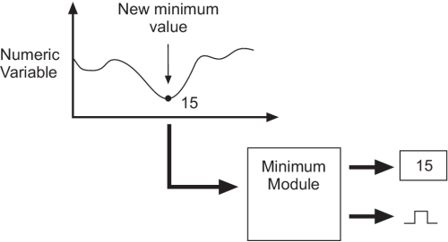
The figure below illustrates the operation of a Minimum Module. As long as the Enable input is on, it monitors a numeric variable and every time the variable reaches a new minimum, the Minimum Module stores that value and generates a pulse.
