Modbus Import Module
The Modbus Import Module reads data from an ION meter or third-party device that supports the Modicon Modbus communications protocol. This data can then be used by other ION modules.
Module icon
![]()
Overview
The module supports the following Modbus data formats:
- 16-bit unsigned
- 16-bit signed
- 32-bit unsigned
- 32-bit signed
- 32-bit unsigned Modulo 10000
- 32-bit signed Modulo 10000
- Packed Boolean
- IEEE Float
Also, "Little Endian" support is available for Float and 32-bit formats.
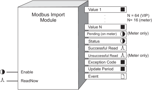
You can configure a Modbus Import Module with up to 64 value output registers per module with Virtual Processor. Some meters have Modbus master capability that you can configure with Designer. There are 16 Value output registers on the meter. There are some registers that are only available on the meter or in the Virtual Processor; these registers are specified in brackets throughout the text.
NOTE: When configured, the Modbus Export Module behaves in a similar fashion to a Modbus controller. However, each module can read data from only one Modbus slave device, over a specified range of its address registers.
The maximum number of Modbus registers the Modbus Import Module can read depends on the Modbus format used.
NOTE: The registers and settings available in this module depend on the device or node you are configuring, as well as its firmware and template versions. Not all registers or settings are available on all devices or the Virtual Processor, and labels may vary.
Inputs
 Enable
This input is used to switch the Modbus Import module on or off. When off is selected the module does not function.
NOTE: Even if the Enable input is not connected, the module will be enabled, by default
 ReadNow
When connected to a trigger source, the module reads data when it detects a pulse at this input. If left unconnected, the module polls the Modbus devices continuously.
Setup registers
 Connection (or COMM Port on some
meters)
This register maps the connection to a setup register on the Modbus Master Options Module. Choose Serial Connection 1-4 or TCP Connection 1-10 (if available).
 Device Name (only on Virtual Processor)
This register contains the address name indicating which Modbus device the module reads data from. This name must first be defined in the Virtual Processor Setup and belong to a Modbus site.
 Slave Addr (slave
address) (only on the meter)
This register contains the numeric address indicating which Modbus device the module reads data from. The valid slave address range is 1-247.
 Reg Addr (register address)
The module communicates to a starting address in the Modbus register map. You specify this starting address in Reg Addr.
 NumReg (number
of registers)
This register specifies the number of Modbus registers read by the module.
 Format
This register defines what format of data the module follows when reading from the Modbus registers. The choices include:
|
Format |
Type |
Range |
# of Modbus registers used |
|---|---|---|---|
|
Unsigned 16B |
Integer |
0 to 65,535 |
1 |
|
Signed 16B |
Integer |
-32,768 to 32,767 |
1 |
|
Unsigned 32B |
Integer |
0 to 4,294,967,295 |
2 |
|
Unsigned 32B Little Endian |
Integer |
0 to 4,294,967,295 |
2 |
|
Signed 32B |
Integer |
-2,147,483,648 to 2,147,483,647 |
2 |
|
Signed 32B Little Endian |
Integer |
-2,147,483,648 to 2,147,483,647 |
2 |
|
Unsigned 32 B-M10k |
Integer |
>0 to 655,359,999 |
2 |
|
Unsigned 32 B M10k Little Endian |
Integer |
0 to 655,359,999 |
2 |
|
Signed 32 B-M10k |
Integer |
-327,689,999 to 327,679,999 |
2 |
|
Signed 32 B M10k Little Endian |
Integer |
-327,689,999 to 327,679,999 |
2 |
|
Packed Boolean |
Integer |
0 to FFFF (Boolean inputs) |
1 |
|
IEEE Float |
Floating Point |
- 3.402823466x1038 to 3.402823466x1038 |
2 |
|
IEEE Float Little Endian |
Floating Point |
- 3.402823466x1038 to 3.402823466x1038 |
2 |
Both Unsigned and Signed 32B-M10k refer to the Modulo10000 formats. This format breaks a 32-bit value into two 16-bit registers, according to the following relationship:
- register_high (higher-order register) = value/10,000
- register_low (lower-order register) = value modulus 10,000
For positive values, the modulo result range is 0 to 9,999. For negative values, the modulo result range is -9,999 to 0.
Hence the 32-bit value can be retrieved by the following calculation:
- value = register_high x 10,000 + register_low
 Scaling
yes indicates that scaling is applied to data before being placed in the value no indicates data is transferred without scaling. No scaling is allowed for IEEE Float, IEEE Float Little Endian or Packed Boolean formats.
 ModbusInMinScale
(Modbus input minimum scale)
If scaling is applicable, this register specifies the lower limit of the Modbus register value.
 ModbusInMaxScale
(Modbus input maximum scale)
If scaling is applicable, this register specifies the upper limit of the Modbus register value.
 IONOutMinScale
(ION output minimum scale)
If scaling is applicable, this register specifies the scaled lower limit of the ION value.
 IONOutMaxScale
(ION output maximum scale)
If scaling is applicable, this register specifies the scaled upper limit of the ION value.
Output registers
 Value 1...Value N
Value 1 register contains the first data value read from the Modbus slave. Value N contains the last data value. The total number of values read from one ReadNow request depends on how you set up the NumReg and Format registers (see the previous section, “Setup Registers”).
 Pending (only on the meter)
Pending output is on if the module is waiting for a response from the slave device.
 Status
This register indicates the status of communication between ION and Modbus protocols. A value of one (ON) indicates that the last communications attempt succeeded; OFF indicates it did not.
 Successful Read
This output generates a pulse whenever the module successfully reads data.
 Unsuccessful Read (only on the meter)
This output generates a pulse whenever the module does not read data because of either a communications error or a Modbus exception.
 Exception Code
This register contains the Modbus exception code returned by the slave when invalid requests are made.
 Update Period
This register contains data indicating the following:
- Polling mode: When the module is polling the Modbus devices, this register specifies the time between updates.
- Event-driven mode: When the module receives a ReadNow request, this register specifies how much time elapse between receiving the ReadNow request and updating the value outputs.
 Event
Event
All events are recorded in the Event register.
Possible events and their associated priority numbers are:
| Event priority group | Priority | Description |
|---|---|---|
| Setup Change | 10 | Input links, setup registers or labels have changed |
| Communications Lost | * | Displays what caused communications loss |
| Resuming Communications | * | Indicates when communications link is re-established |
| * The priority of this event depends on how you configure the EvPriority setup register. | ||
The Event output register stores the following information for each ION event: time stamp, priority, cause, effect, and any values or conditions associated with the cause and effect.
Modicon Modbus
Four classes of Modbus data, namely Coil, Input, Input Register, and Holding Register, are supported by the Modbus Import Module. Coils and Inputs are singlebit registers used to indicate on (1) or off (0) conditions.
NOTE: For further details, refer to your Modicon Modbus Communications Protocol document, or visit their website at www.modicon.com
Input Registers and Holding Registers are 16-bit registers used to store and retrieve data. The following list shows results if specify the Reg Addr to begin with:
- zero (0), data is imported as Coil Status
- one (1), Input Status
- four (4), Holding Registers
- three (3), Input Register
The following table outlines the function codes that the Modbus Import module uses to support the classes of Modbus data:
|
Function Name |
Function Code |
Register Address |
|---|---|---|
|
READ_COIL_STATUS |
01 |
0XXXX(X) |
|
READ_INPUT_STATUS |
02 |
1XXXX(X) |
|
READ_HOLDING_REGISTERS |
03 |
4XXXX(X) |
|
READ_INPUT_REGISTERS |
04 |
3XXXX(X) |
NOTE: The module automatically chooses the Function Code based on the Reg Addr setup register value.
The following table outlines the different Modbus formats supported by the Modbus Import module, as well as the maximum number of registers the Modbus Import module is able to read per read request:
|
Modbus Format |
Single Register |
Multiple Registers |
||
|---|---|---|---|---|
|
Virtual Processor |
Meter |
Virtual Processor |
Meter |
|
|
Signed 16B |
64 registers / 64 values |
16 registers / 16 values |
64 registers / 64 values |
16 registers / 16 values |
|
Unsigned 16B |
||||
|
Signed 32B |
124 registers / 62 values |
32 registers / 16 values |
124 registers / 62 values |
32 registers/ 16 values |
|
Signed 32B Little Endian |
||||
|
Unsigned 32B |
||||
|
Unsigned 32B Little Endian |
||||
|
Signed 32B-M10k |
||||
|
Signed 32B-M10k Little Endian |
||||
|
Unsigned 32B-M10k |
||||
|
Unsigned 32B-M10k Little Endian |
||||
|
IEEE Float |
||||
|
IEEE Float Little Endian |
||||
|
Packed Boolean |
4 registers / 64 values |
1 register / 16 values |
4 registers/ 64 values |
1 register/ 16 values |
The following sections illustrate how the Modbus Import module maps its output Value registers to the Modbus register map, according to the chosen Modbus format.
Coil and Input Status Format
For Modbus coil and input registers, the Modbus Import module maps its output Value register in a similar fashion to the 16-bit signed or 16-bit unsigned format.
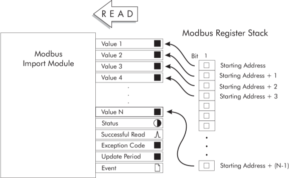
Holding and Input Register Formats
Little Endian
For all 32-bit formats (IEEE Float and Signed, Unsigned 32-bit and M10k), Little Endian reverses the two registers (not the bits within the registers) where the data is written. For example, data from the specified starting address of the Modbus register map is copied into the Value 2 output register and the remaining data is copied into the Value 1 output register.
Signed 16B or Unsigned 16B
UNSCALED
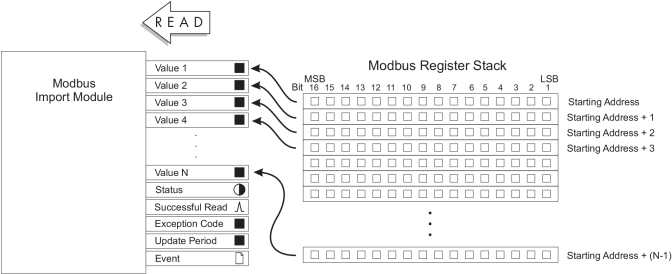
The module takes data from the specified starting address of the Modbus register map and copies it into the Value 1 output register; the remaining registers are coped into Value 2,..., Value N.
SCALED
The module takes data from the specified starting address of the Modbus register map, places it in a temporary register, applies scaling specified in the module’s setup registers, then transfers the result into the Value 1 output register.
The following 16-bit Modbus Register Map illustrates how the module maps its Value outputs to the Modbus register map:
16-bit Modbus Register Map
IEEE Float
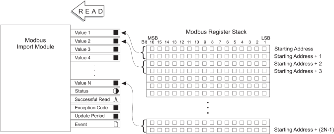
IEEE Float is a floating point format. It does not support scaling. The module takes data from the specified starting address and the adjacent higher address of the Modbus register map. It copies the contents of the first address into the 16 most significant bit positions on Value 1 output register and copies the contents of the second address into the 16 least significant bit positions of the Value 1 output register. Value 1 is interpreted as a floating point number. See the next illustration (32-bit Modbus Register Map) for details.
Signed 32B or Unsigned 32B
UNSCALED
The module takes data from the specified starting address and the adjacent higher address of the Modbus register map. It copies the contents of the first address into the 16 most significant bit positions on Value 1 output register and copies the contents of the second address into the 16 least significant bit positions of the Value 1 output register.
SCALED
The module takes data from the specified starting address and the adjacent higher address of the Modbus register map. It copies the contents of the first address into the 16 most significant bit positions of a temporary register and copies the contents of the second address into the 16 least significant bit positions of this temporary register. The module then applies the scaling you specified in the module’s setup registers and transfers the result into Value 1 output register.
The 32-bit Modbus Register Map illustrates how the module maps its Value outputs to the 32-bit Modbus register map.
Signed 32B-M10k or Unsigned 32B-M10k
The module maps its Value output registers to the Modbus register map in a similar fashion as the 32-bit signed or 32-bit unsigned format.
UNSCALED
The module takes data from the specified starting address and the adjacent higher address of the Modbus register map. It then takes the contents of the first address (most significant) and multiplies this value by 10000. It then takes the product and adds the contents of the second address (least significant). The result is placed into the Value 1 output register. The module repeats this process for the remaining Value registers.
SCALED
The module takes data from the specified starting address and the adjacent higher address of the Modbus register map. It takes the contents of the first address (most significant) and multiplies this value by 10000. It then takes the product and adds to it the contents of the second address (least significant). The result is placed into a temporary register.
The module then applies scaling specified in the module’s setup registers and transfers the result into Value 1 output register. The module repeats this process for the remaining Value registers.
32-bit Modbus Register Map
Packed Boolean
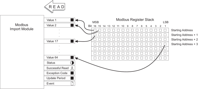
The module takes data from the specified starting address and copies the contents of the most significant bit into the Value 1 output register. It then takes the contents of the second most significant bit from the starting address and copies it into the Value 2 output register, etc., until the least significant bit is copied into the Value 16 output register.
For a module on the Virtual Processor, remaining registers are copied into the next available outputs. The most significant bit of the second register is copied into Value 17 output register, etc. See the Packed Boolean Modbus Register Map below:
Packed Boolean Modbus Register Map (VIP)
Responses to special conditions
The following table summarizes how the module behaves under different conditions.
| Condition | Response of output registers |
|---|---|
| If the Enable input is not available | The Value 1…N are not available. The Status register is set to N/A. Pending = N/A |
| After the module is re-linked or its setup registers are changed | The Value 1…N, Status, Exception Code and Update period registers are not available. Pending = NO |
| When the device is started or powered-up (either the first time, or after a shut-down) | The Value 1…N, Status, Exception Code and Update period registers are not available. Pending = NO |
| Receive timeout (i.e. Modbus Import module sends a request, but does not receive a reply) | Output registers holds the current values. The Virtual Processor displays a message in its window. The meter pulses an unsuccessful read. |
Detailed module operation
To set up communications between the Virtual Processor and Modbus, you must first enter the Modbus device address information in the Virtual Processor Setup utility. Select a unique name for the Modbus device and map this string variable to the Modbus device’s address. You use this name later on when setting up the module’s Device Name setup parameter.
To set up communications between the meter and Modbus, use Designer to configure the communications port (COM port and baud rate) on the Modbus Master capable meter. Ensure the Modbus Master protocol is active on the communications channel that connects the Modbus master capable meter to a slave device on the Modbus network.
The Modbus Import module is automatically enabled after you have added, set up and saved your framework. Linking the Enable input gives you the option to turn the module on or off.
NOTE: The frequency of polling depends on a number of variables (e.g. baud rate, number of devices on the communication loop, etc.); devices are polled in a sequential manner.
If the ReadNow input is not connected, the module starts polling the registers on the Modbus device. Triggering the ReadNow input instructs the module to immediately send a read request to the Modbus Slave device. When the request is serviced, the values from the Modbus registers are copied to the Value output registers of the module. The Status output register indicates if the Modbus to ION communications line is active.
The Successful Read output register generates a pulse whenever the module completes a successful transfer of information from the Modbus slave to the master. The Value 1 through Value N output registers is updated for each read cycle.