MultiState Display Module
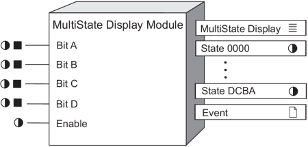
This module provides an efficient means of using up to four binary or numeric inputs to define and display 16 states. This module is only available in the VIP.
Module icon
![]()
Overview
The 16 states represent every combination of true or false each of the inputs can have. The input values are represented in the order DCBA where a true value is represented by an alphanumeric letter, and a false value by the number 0.
The primary output of this module provides a means of displaying the current state based on the DCBA input combination which can be linked to a status object in Vista and the Web-based Diagrams application. In addition, an explicit binary status output for each state is provided both for display purposes and/or the ability to trigger a setpoint/alarm when a desired state becomes active or inactive.

Inputs

 Bit A, Bit B, Bit C, Bit D
Link the input to represent the specified bit in the binary number DCBA. The value can be a boolean (true/false) or a numeric variable register (non-zero = true, zero= false) for convenience when used with an Arithmetic module calculation.
 Enable
This input enables or disables the module. Disabling the module forces the output values to not available, and the module stops processing the Bit inputs.
This input is optional; if you leave it unlinked, the module is enabled by default.
Setup registers
 State 0000 - State DCBA
| When Setup Register holds | Bit value is true for | Bit value is false for |
|---|---|---|
| State 0000 | - | D, C, B, A |
| State 000A | A | D, C, B |
| State 00B0 | B | D, C, A |
| State 00BA | A, B | D, C |
| State 0C00 | C | D, B, A |
| State 0C0A | C, A | D, B |
| State 0CB0 | C, B | D, A |
| State 0CBA | C, B, A | D |
| State D000 | D | C, B, A |
| State D00A | D, A | C, B |
| State D0B0 | D, B | C, A |
| State D0BA | D, B, A | C |
| State DC00 | D, C | B, A |
| State DC0A | D, C, A | B |
| State DCB0 | D, C, B | A |
| State DCBA | D, C, B, A | - |
Output registers
 MultiState Display
This output register is used to display the appropriate programmable label (see setup registers) for the present combination of Bits DCBA input values. This enumerated register will supply all programmed labels to Vista for convenient programming of the desired status object.
 Status 0000 to Status DCBA
These output registers provide explicit Boolean indicators of the active/inactive status of each state. These can be used explicitly for displaying states of interest, or as part of a framework in conjunction with a setpoint module for the purpose of generating an alarm and/or notification.
 Event
Event
Any events produced by the MultiState Display Module are written into this register.
Possible events and their associated priority numbers are shown in the following table.
| Event priority group | Priority | Description |
|---|---|---|
| Setup Change | 10 | Input links, setup registers or labels have changed. |
Responses to special conditions
| Condition | Response of output registers |
|---|---|
| If any of the Bit input values go not available | All output registers are marked not available, as the actual state is uncertain. |
| If a Bit input is left unlinked | The input is interpreted as a zero. For example, if you only link Bit A and Bit B (four possible states), Bit C and Bit D default to a zero value. |
Detailed module operation
The MultiState Display Module enables the representation of changes in state. You can use a single Status object in Vista to display the various state changes.
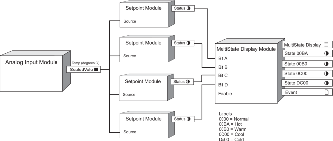
The following example describes how changes in temperature can be represented by a single Status object in Vista.
Assume that the temperature on a floor of a building is being measured, and the hardware IO of the device connected to the temperature monitoring equipment provides a temperature value to the output register of an Analog Input module.
The output register of the Analog Input module is linked to the input registers of the Setpoint modules that have been added to a VIP in Designer. Each Setpoint module triggers a state change when the temperature value reaches thresholds of 18C, 20C, 24C and 27C, respectively.
The Setpoint modules are configured as follows:
- Setpoint 1: SP1 High Limit > 27C, and Low Limit > 27C with a Custom label of “HighHigh”.
- Setpoint 2: SP2 High Limit > 24C and Low Limit > 24C with a Custom label of “High”.
- Setpoint 3: SP3 High Limit < 20C and Low Limit < 20C with a Custom label of “Low”.
- Setpoint 4: SP4 High Limit < 18C and Low Limit < 18C with a Custom label of “LowLow”.
The output registers of each Setpoint module are linked to Bit A, B, C and D input registers, respectively, of the MultiState Display Module.
The Setup registers in the MultiState Display Module are configured, and the labels updated as follows:
| Setup Register | Label |
|---|---|
| MD1 State 0000 | Mid |
| MD1 State 00BA | HH |
| MD1 State 00B0 | H |
| MD1 State 0C00 | L |
| MD1 State DC00 | LL |
The bit value 0000 of the Mid Setup register indicates that no states are ‘True’, and therefore the temperature is in the accepted, normal range of 20C to 24C.
In Vista, you can use a Status object to visually indicate the changes in the temperature thresholds by linking it to the MultiState Display output register and assigning images representing the detected temperature threshold on the floor.

Link the status object to the MultiState Display object and specify custom images representing the temperature values, where 0000 is normal, 00BA is hot, 00B0 is warm, 00C0 is cool and DC00 is cold.
NOTE: GIF, JPG and PNG images need to be in \config\diagrams under the product’s installation
location or they will not be shown in the Web-based Diagrams application.
When a specified temperature threshold is reached, the Status output register on the Setpoint module with the corresponding threshold settings is set to on, which then sets to true the bit input register in the MultiState Display Module.
For example, if the temperature is 22C, then all bits are false and the Output Status 0000 is true. The Status object in Vista displays the image used with the output status 0000 to depict a normal temperature.
If the temperature is 25C, then only Bit B is true and the Output Status 00B0 is true. The Status object displays the image used with the output status 00B0 to depict a warm temperature.
However, if the temperature is 28C, then both Bit A and Bit B are true and the Output Status is 00BA. The Status object in Vista displays the image used with condition 00BA to depict a hot temperature.