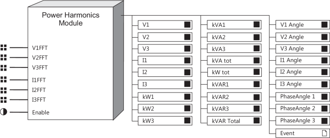
Power Harmonics Module
The Power Harmonics module provides an in-depth analysis of power system parameters for a selected harmonic.
Module icon
![]()
Overview
The module measures voltage and current levels for the selected harmonic, and derives kW, kVAR, kVA, Voltage Angle, Current Angle and Phase Angle values for each phase.

NOTE: The registers and settings available in this module depend on the device or node you are configuring, as well as its firmware and template versions. Not all registers or settings are available on all devices or the Virtual Processor, and labels may vary.
Inputs
 V1FFT, V2FFT, V3FFT
The V1FFT, V2FFT and V3FFT inputs are fixed. They receive phase voltage information from the FFT module.
 I1FFT, I2FFT,
I3FFT
The I1FFT, I2FFT, and I3FFT inputs are fixed. They receive phase current information from the FFT module.
 Enable
All Power Harmonics modules have one programmable input called Enable. When this register is set to true, the module is enabled. When it is set to false, the module is disabled; it ceases to calculate power values and its output registers become N/A. This input is optional; if you leave it unlinked, the module is enabled by default.
Setup registers
 Harmonic Number
This register specifies which harmonic to calculate parameters for. Any harmonic from the fundamental to the device’s maximum can be selected. The fundamental, or 1st harmonic, is selected by default.
Output registers
 V1, V2 and V3
These numeric output registers hold the RMS phase voltage values for the harmonic specified in the Harmonic Number setup register.
 I1, I2 and I3
These numeric output registers hold the RMS phase current values for the harmonic specified in the Harmonic Number setup register.
 kW1, kW2 and kW3
These numeric registers hold the kW values for each phase at the harmonic specified in the Harmonic Number setup register.
 kW Total
This numeric register holds the total kW value for all phases at the harmonic specified in the Harmonic Number setup register.
 kVAR1, kVAR2 and
kVAR3
These numeric registers hold the kVAR values for each phase at the harmonic specified in the Harmonic Number setup register.
 kVAR Total
This numeric register holds the total kVAR value for all phases at the harmonic specified in the Harmonic Number setup register.
 kVA1, kVA2 and
kVA3
These numeric registers hold the kVA values for each phase at the harmonic specified in the Harmonic Number setup register.
 kVA Total
This numeric register holds the total kVA value for all phases at the harmonic specified in the Harmonic Number setup register.
 V1 Angle, V2 Angle and V3 Angle
These numeric registers hold the voltage angle values (in degrees) for each phase at the harmonic selected in the Harmonic Number setup register. Voltage angles are given with respect to the position of the V1 fundamental harmonic.
 I1 Angle, I2 Angle and I3 Angle
These numeric registers hold the current angle values (in degrees) for each phase at the harmonic selected in the Harmonic Number setup register. Current angles are given with respect to the position of the V1 fundamental harmonic.
 Phase Angle1, Phase Angle 2 and Phase
Angle 3
These numeric registers hold the phase angle value, in degrees, for each phase at the selected harmonic. The phase angle is given as the difference between the current and voltage angles for each phase.
 Event
Event
All events produced by a Power Harmonics Module are written into this register.
Possible events and their associated priority numbers are shown in the following table:
| Event priority group | Priority | Description |
|---|---|---|
| Setup Change | 10 | Input links, setup registers or labels have changed. |
The Event output register stores the following information for each ION event: time stamp, event priority, event's cause, event's effect, and conditions associated with the event's cause and effect.
Responses to special conditions
The following table summarizes how the Power Harmonics Module behaves under different conditions.
| Condition | Response of output registers |
|---|---|
| If the Enable input is off or N/A | The output registers are N/A. |
| When the device is started or powered-up (either the first time, or after a shut-down). | The output registers are N/A. |
Detailed module operation
The Power Harmonics Module receives the phase voltage and current values measured by the IED. From these values, kW, kVA, kVAR, voltage angles, current angles and phase angles are calculated for the harmonic specified in the Harmonic Number setup register. Using these values, you can determine the magnitude and direction of harmonic power flow at any harmonic from the first to the 63rd.
The basic procedure for analyzing harmonic power flow is as follows:
- Choose the harmonic you want to analyze by specifying its number in the Harmonic Number setup register.
- Use software or the device’s display to view the values in the module’s output registers.