Pulser Module
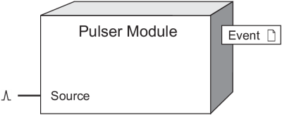
The Pulser module serves as a intermediary between other module’s pulse output registers and a hardware output channel on the device.
Module icon
![]()
Overview
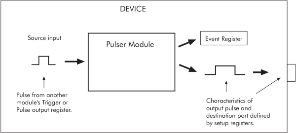
The module converts the instantaneous pulses to pulses or transitions on a hardware output channel. You must specify whether the output is a transition or complete pulse, and you must indicate if it will pulse high or low. You must also select on which hardware port the pulses will appear (for example, digital output port number 3).
For each pulse received at the Source input, a single pulse is sent to the specified hardware output channel.
Your meter’s digital and analog outputs may change state when being configured, during an option module reset or power cycle, or during firmware or framework upgrade. Refer to your meter’s documentation for additional information.
 warning
UNEXPECTED DIGITAL OUTPUT PULSE
Do not use this device for critical control or protection applications where human or equipment safety relies on the operation of the control circuit.
Failure to follow these instructions can result in death, serious injury, or equipment damage.

NOTE: The registers and settings available in this module depend on the device or node you are configuring, as well as its firmware and template versions. Not all registers or settings are available on all devices or the Virtual Processor, and labels may vary.
Inputs
 Source
All Pulser modules have one input called the Source. This input can be the pulse output register from any other module. It is monitored for a pulse and when one is present, it sends a pulse to the specified hardware output channel.
Setup registers
 PulseWidth
The PulseWidth numeric bounded register specifies the minimum pulse on time (the time period that an LED is lit or relay is closed). When the OutputMode is set to pulse, the PulseWidth also specifics the off time that follows the on time. The PulseWidth register is stored in seconds with a resolution of milliseconds.
 OutputMode
This register specifies whether the output is a complete pulse (pulse) or a transition pulse (kyz).
 Polarity
If you have selected a complete pulse as the OutputMode, this register defines the output polarity of the pulses. It has no effect if you selected transition mode.
 Port
Port
This register specifies which hardware port the output appears on. Refer to your device’s documentation for a list of available ports.
notice
HAZARD OF MISAPPLICATION (MISUSE)
Because mechanical relays have limited lifetimes, mechanical KYZ relays are typically not suitable for energy pulsing applications. For energy pulsing applications, consider using Form A outputs in KYZ mode.
Failure to follow these instructions can result in equipment damage.
Output registers
The primary effect of the Pulser module is not to send a value to an output register but to send a pulse to the actual hardware. This makes it slightly different from most of the other modules. Pulser modules do however generate events and thus, they have an Event register.
NOTE: You do not need to use a Digital Output module to control the hardware device; the Pulser module can control the hardware device itself.
 Event
Event
All events are recorded in the Event register. Possible events and their associated priority numbers are:
| Event priority group | Priority | Description |
|---|---|---|
| Setup Change | 10 | Input links, setup registers or labels have changed. |
The Event output register stores the following information for each ION event: time stamp, priority, cause, effect, and any values or conditions associated with the cause and effect.
Responses to special conditions
The following table summarizes how the module behaves under different conditions.
| Condition | Response of output registers |
|---|---|
| After the module is re-linked or its setup registers are changed | Any pulses in progress are discarded. |
| When the device is started or powered-up (either the first time, or after a shut-down) | No pulses are sent to the hardware port, and all pending pulses are discarded. |
Detailed module operation
The figure below illustrates the operation of the Pulser module.

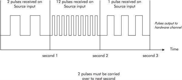
Each second, the Pulser module determines how many pulses it has received on its Source input and outputs a like number of pulses to the specified hardware output channel. Because the PulseWidth setup register limits the output pulse to a minimum width, the Pulser module may not always be able to output a pulse for every pulse it receives on its Source input. In these cases, the extra pulses are sent to the hardware output channel in the next second. In cases where the Pulser module can output the correct number of pulses, these pulses are spread evenly throughout the second.
In the figure below, the PulseWidth is set to 0.05 seconds and the OutputMode is set to pulse. This means that a maximum of 10 pulses can be output to the hardware channel in one second.

Note that in the first second, the two output pulses are spread evenly across the second, rather than compressed into the first or last portion of the second.
KYZ Mode
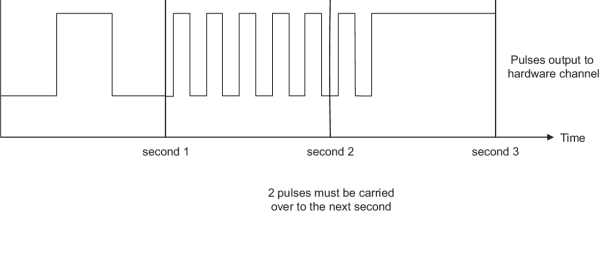
If the OutputMode setup register is set to kyz, the Pulser module will behave as illustrated below.

Notice that the PulseWidth now becomes the minimum amount of time that the module will wait before recognizing the next pulse. If pulses are received before the PulseWidth time has elapsed, they will be queued and sent on the next cycle.