Transient Module
The Transient module monitors the waveforms for all voltage phases and determines the magnitude and duration of a transient when one is detected on any phase.
Module icon
![]()
Overview
You can specify how large a disturbance has to be before it is considered a transient and recorded.
The Transient module can be used to detect ITI (CBEMA)-type disturbances. The magnitude and duration information provided by this module can be displayed in a CBEMA plot using Vista to analyze the voltage disturbance characteristics of your power system.
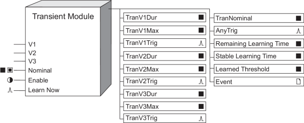
You can configure the Transient module to learn what threshold a disturbance needs to reach to be considered a transient, and then either to place the learned threshold value in the Learned Threshold register for review or to begin using the learned threshold value automatically. If enabled, learning can occur even if the module itself is not enabled.
NOTE: The registers and settings available in this module depend on the device or node you are configuring, as well as its firmware and template versions. Not all registers or settings are available on all devices or the Virtual Processor, and labels may vary.
Inputs
 V1-V3
V1-V3
These inputs are linked to the Data Acquisition module and cannot be changed.

 Nominal (nominal voltage)
This input specifies the nominal voltage for your power system. By default, this input is linked to the NomVolts setup register in the Sag/Swell module, which holds the nominal system voltage used in your system. The threshold value (entered in the Threshold setup register) is specified as a percentage of the Nominal value, so this input directly affects the module’s tolerance. If your power system’s typical voltage levels vary from the NomVolts setting, you can link this input to any other register that provides a numeric value. Transient modules in most systems operate properly with this register linked to NomVolts. Linking this input is mandatory.
NOTE: Nominal refers to the primary power system voltage (line-to-line voltage for Delta systems and line-to-neutral voltage for Wye systems). The primary power system voltage is sometimes different than the PT Primary setup register value; i.e. when the PT Primary is used to indicate winding ratio rather than primary voltage.
 Enable
When this input is true, the module is enabled; when it is set to false, the module is disabled and the output registers that are not related to learning become not available. This input is optional; if you leave it unlinked, the module is enabled by default.
 Learn Now
When this input is pulsed, it starts the learning process and begins the learning period. If a pulse is received while learning is in progress, the current learning period is aborted, all data in the learning-related output registers is reset and a new learning period begins.
This input must be linked for learning to be enabled. If this input is pulsed, learning occurs even if the module is not enabled. Learning is stopped, and learning-related outputs become not available, when any setup of the module changes. To disable learning completely, disconnect this input.
Setup registers
 Threshold
This numeric bounded register allows you to specify how much the voltage can deviate from normal before a transient is recorded. The magnitude required for a transient to be recorded is specified as a percentage of the nominal voltage, plus 100. For example, a value of 120 causes the module to detect transients with a deviation that is greater than 20% from the nominal; transients with a deviation of 20% or less are not detected.
If learning is enabled, this register is overwritten by the learned values, either when you install the values in manual mode or when learning is complete in automatic mode.
 EvPriority
This register allows you to assign a priority level to the events generated by the Transient module (see the Event output register description). An event is generated when a transient is detected.
 Learn Install
Mode
This register specifies how the learned values are installed:
- manual: Learning occurs but the module is not automatically configured with the learned values when learning is complete. The learned values are placed in the learned output registers to be manually installed.
- automatic: Learning occurs and the learned values are placed in the learned output registers. The module automatically installs and starts using the learned values when learning is complete.
Once the learned values are installed, either manually or automatically, the value of the learned output registers becomes not available.
 Learn Duration
This register specifies the learning duration in minutes. The allowable range is 1 to 300. The default is 30.
 Detection Mode
This register specifies how the meter threshold functions:
- waveshape: The Transient module predicts what the shape of a “normal” waveform should be for each voltage phase. These predicted normal waveforms are compared to the actual real-time phase voltage waveforms that are measured by the meter. If the actual waveform deviates from the predicted waveform by an amount greater than the Threshold (both above and below), a transient is recorded.
- absolute: The threshold required for a transient to be recorded is specified as a percentage of the nominal peak voltage.
Output registers
 TranV1Dur, TranV2Dur, TranV3Dur
These numeric registers contain the duration of any transient detected on V1, V2 or V3, respectively, given in seconds.
 TranV1Max, TranV2Max, TranV3Max
These numeric registers contain the maximum peak magnitude of the transient on V1, V2 or V3, respectively, given as a percentage of Nominal. For example, a maximum 20% deviation on V1 with respect to the Nominal (in either the positive or negative direction) will be reported as TranV1Max=120.
 TranV1Trig, TranV2Trig, TranV3Trig
These registers output a pulse if a transient is detected on V1, V2 or V3 respectively.
 TranNominal
This register holds the value at the Nominal input that was in effect at the beginning of a disturbance.
 AnyTrig
If a transient is detected on any phase, this register outputs a pulse. This trigger is in addition to any of the individual phase triggers.
 Remaining Learning Time
This register contains the remaining learning time, in seconds. It counts down from the Learn Duration to 0 (zero). When this value reaches zero, learning is complete. If the Stable Learning Time reaches one-quarter of the Learn Duration, this register jumps to zero and learning is complete. If learning has not started, the value of this register is not available.
 Stable Learning Time
This register contains the number of seconds that have elapsed since a change in the learned Threshold value. When this value is equal to one-quarter of the Learn Duration, learning is complete. If learning has not started, the value of this register is not available.
 Learned Threshold
This numeric register contains the learned value for the Threshold setup register. When learning is in progress, this register is continually updated. This register becomes not available and learning stops when any setup is changed, for example, when the Learn Now input is unlinked or the value of the Threshold register is changed.
 Event
Event
All events are recorded in the Event register.
Possible events and their associated priority numbers are:
|
Event priority group |
Priority |
Description |
|---|---|---|
|
Setup Change |
10 |
Input links, setup registers or labels have changed, or learned values were installed automatically. |
|
Setpoint |
* |
Transient detected; magnitude is reported. |
|
Install Failed |
10 |
Automatic installation of a learned value failed because the value was invalid; invalid value is reported. |
|
Unable to Install |
30 |
Automatic installation of learned values failed for an unknown, unrecoverable reason. |
|
* The priority of this event is determined by the value in the EvPriority setup register. |
||
The Event output register stores the following information for each ION event: time stamp, priority, cause, effect, and any values or conditions associated with the cause and effect.
Responses to special conditions
The following table summarizes how the Transient module behaves under different conditions.
| Condition | Response of output registers |
|---|---|
| If the Source inputs are not available | All output registers are not available. |
| If the Nominal input is zero | All output registers are not available. |
| If the Enable input is off | All output registers that are not related to learning are not available. |
| When the device is started or powered up (either the first time, or after a shutdown) | All output registers are not available. |
| If learning is not in progress and no learned values are waiting to be installed | Learned output registers are not available. |
| If V1, V2, or V3 or the Nominal input are not available, or there is any change in the module setup | Learning stops and is reset, and the learned output registers are not available. |
Detailed module operation — Waveshape mode
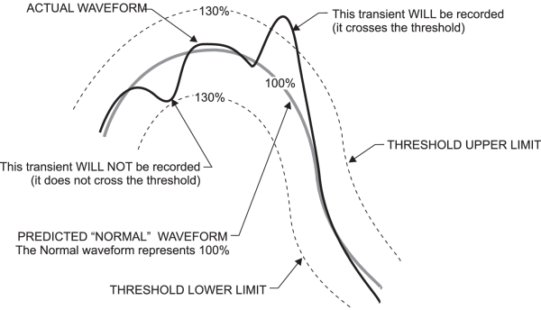
When Detection Mode is waveshape, the Transient module predicts what the shape of a “normal” waveform should be for each voltage phase. These predicted normal waveforms are compared to the actual real-time phase voltage waveforms that are measured by the meter. If the actual waveform deviates from the predicted waveform by an amount greater than the Threshold, a transient is recorded.
The following diagram illustrates the normal and actual waveforms, and the use of the Threshold to determine whether or not a disturbance is considered a transient. A Threshold value of 130 is shown in the diagram.
Threshold calculation — Waveshape mode
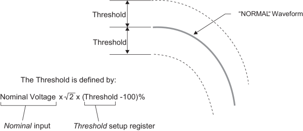
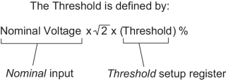
The threshold is calculated using the values in the module’s Nominal input and Threshold setup registers. The width of the threshold is determined by applying the value in the Threshold register as a percentage of the Nominal peak voltage. Nominal peak voltage is derived from the value at the Nominal input, as shown below. Note that the threshold is applied in both directions from the predicted normal waveform.
Transient module output values — Waveshape mode
The magnitude of a transient is reported as a percentage of nominal, added to 100. For example, if a transient is detected on V1 that is 40% larger in magnitude than the normal voltage, the TranV1Max register holds a value of 140. The duration is reported as the time in seconds during which the phase voltage is outside the threshold level.
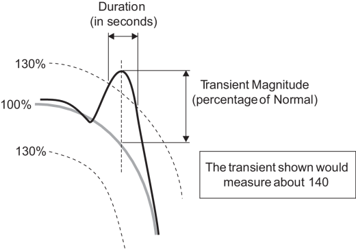
Magnitude is reported as a percentage of nominal plus 100 to allow easy plotting of transient activity on CBEMA plots in Vista.
Some experimentation may be required to determine the correct value for the Threshold setup register. If it is set too low, common waveform distortions may be interpreted as transients. If the Threshold is set too high, important transients could be missed.
Detailed module operation — Absolute mode
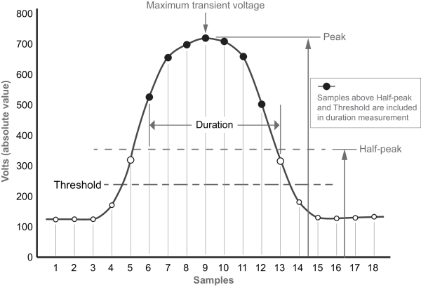
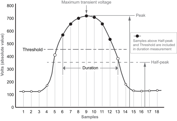
When Detection Mode is absolute, the Transient module records a transient when the waveform is greater than the Threshold register.
The following diagrams illustrate the use of the Threshold register to determine whether or not a disturbance is considered a transient. A Threshold value of 140 is shown in the first diagram, while a value of 280 is shown in the second diagram.
Power tolerance curves
The CBEMA curve is a power tolerance curve that describes what types of disturbances electrical equipment can typically ride through and what types can cause equipment failure or damage. It plots the magnitude of the disturbance (in percentage) on the Y-axis and the duration of the disturbance on the X-axis. Disturbances that fall within the envelope defined by the upper and lower curve are typically not harmful to electrical equipment; disturbances that fall outside the envelope may disrupt or damage the equipment.
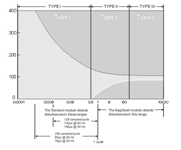
NOTE: The start of the transient detection window depends on the meter’s sampling rate. Refer to your device’s documentation.
Analyzing data with Vista
You can plot transient data on a CBEMA curve using Vista. Connect the magnitude and duration output registers of the Transient module (for example, TranV1max and TranV1dur) to the Source inputs of a Data Recorder module, and trigger the Data Recorder by connecting the Transient module’s AnyTrig output to the Data Recorder’s Record input. The Data Recorder module then records magnitude and duration data when a transient occurs.
You can also capture the waveform that contains the transient activity by using the Transient module to trigger a Waveform Recorder module. Link the Transient module’s trigger output for the voltage phase you’re interested in (for example, TranV1Trig) to the Record input of the Waveform Recorder module. Ensure that the Waveform Recorder module’s Source input is linked to the appropriate phase voltage output on the Data Acquisition module, and set the Depth and Record Delay setup registers appropriately (refer to the Waveform Recorder module description). When a transient is detected on this phase, the corresponding waveform is recorded.
You can also use a phase trigger (TranV1Trig, TranV2Trig or TranV3Trig) to trigger one or more Counter modules to keep track of the number of transients that occur on each voltage phase.