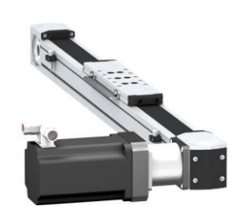
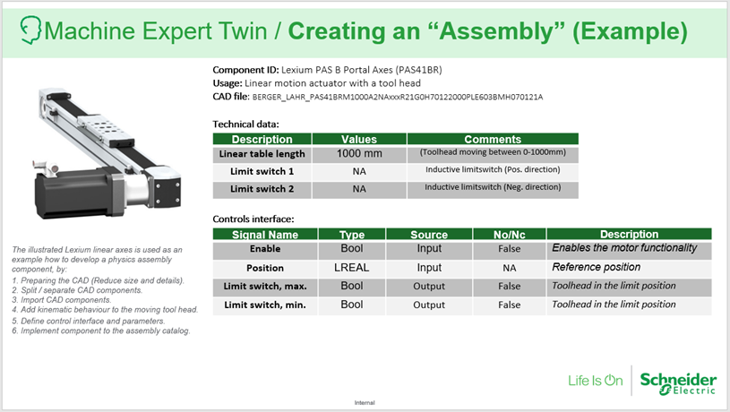
In some projects adding a custom component will be needed to make a complete model. In this workflow guide we will show how a C# developer can add a Lexium PAS B Portal Axes (PAS41BR). The whole process for a seasoned C# and EcoStruxure Machine Expert Twin developer is about one day to have the component ready for testing.
Step 1 - Configuring the project
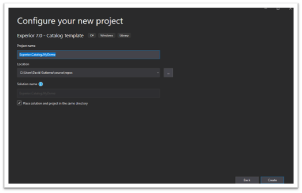
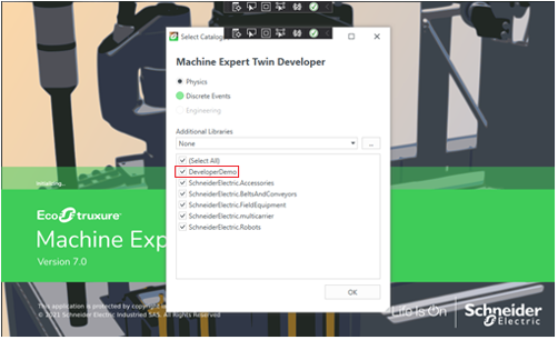
First step is to create a catalog, so we can view the component in the catalog in EcoStruxure Machine Expert Twin. For all of these steps we use Visual Studio for this preliminary step-
We have a template for making catalogs (you can find a guide to finding the templates here HERE) that we select when starting the new project in Visual Studio.
The first important step is to make sure we use the proper naming convention for the new catalog.
When EcoStruxure Machine Expert Twin is starting up, it will scan its folder for .dll files with the naming convention ‘Experior.Catalog.XXXX’.
In this example we name it ‘Experior.Catalog.DeveloperDemo
Note: If we wish to maintain the same naming structure as the already constructed and tested Schneider catalogs we should call all future .dll ‘Experior.Catalog.SchneiderElectric.XXXX’.
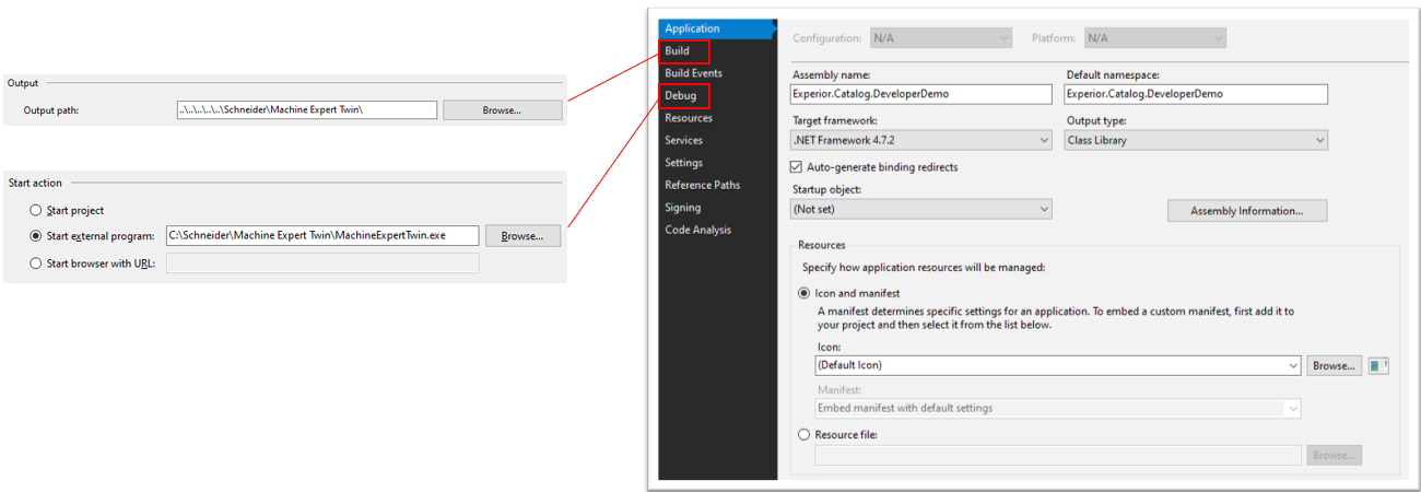
Now, open up the project properties window and use the following setup:
Assembly name
Default namespace – we suggest you use the same same as assembly to minimize any confusion
Output path – where the finished .dll is placed on your computer.
Debug – Setting EcoStruxure Machine Expert Twin as the program working on the .dll
Setting up the Lexium in the catalog
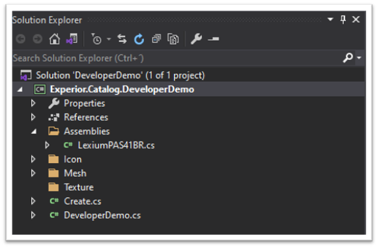
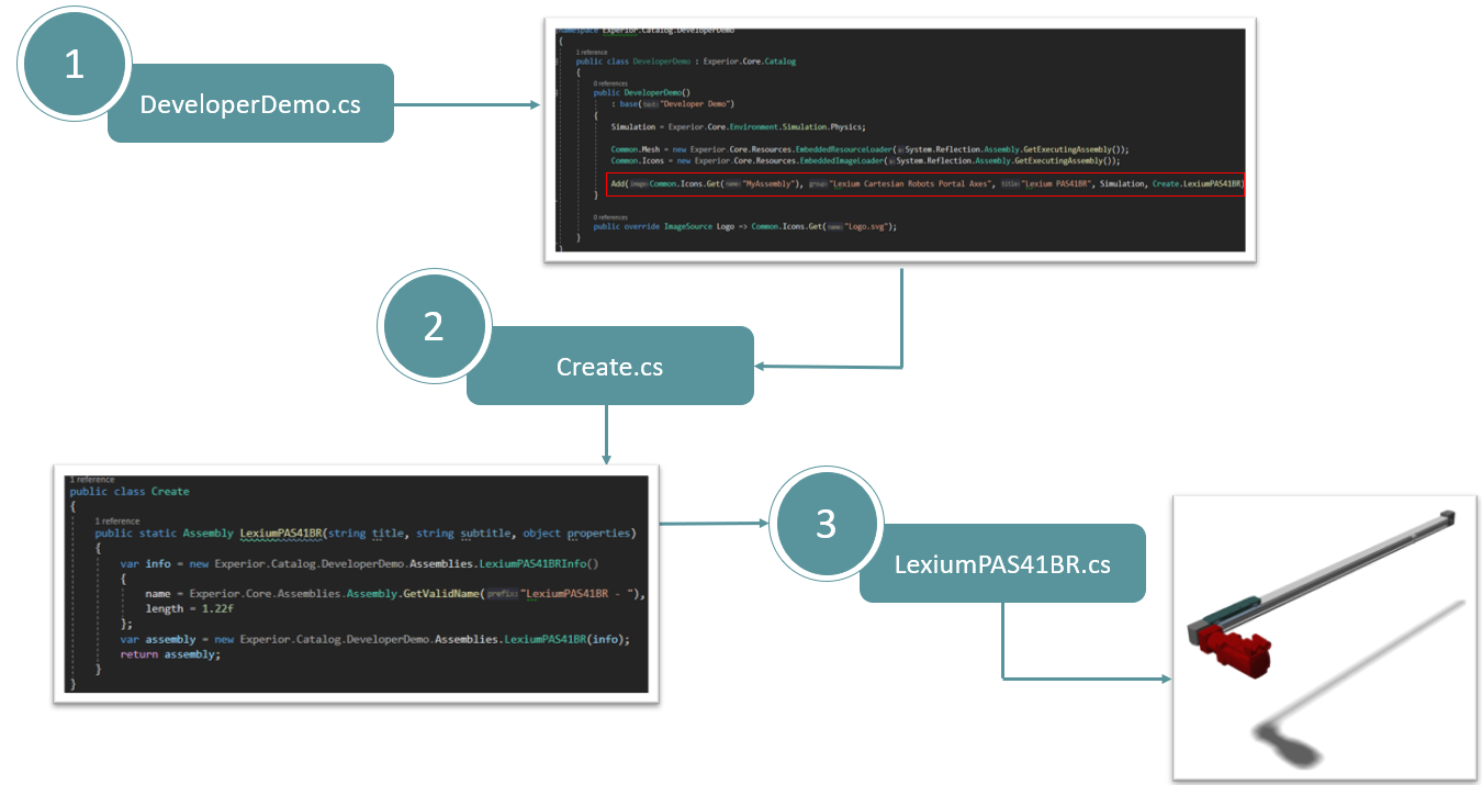
When EcoStruxure Machine Expert Twin is executed, it will instantiate the class DeveloperDemo.cs. This class is used to add the components to the catalog.
As soon as the user drops a component into the scene, the static method passed as an argument in the Add method will be called (LexiumPAS41BR), creating an instance of the component.
An instance of the component is created.
Creating the component
Now we can use the information that we have ready at hand to start creating the component proper.
Add a new item to the folder Assemblies.
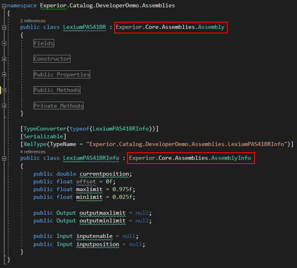
The new component class must use inheritance from the Assembly class.
Info class is used to store information about the component (e.g., length, width, height, PLC signals, new types which are serializable).
Basic representation
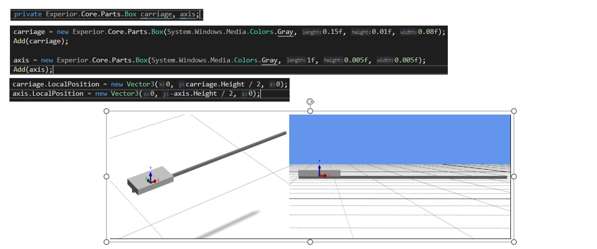
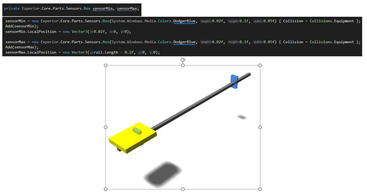
Now we are ready for the early construction of the component. In early stages functionality and correct behaviors are prioritized in creating a model, as opposed to implementing the design, with the CAD-drawings, at this early stage. The basic representation is in this case constructed using boxes and cylinders – These parts are ready available to us in EcoStruxure Machine Expert Twin. In the pictures below you can see the creation of the basic geometries and the positioning in the local coordiante system.
Previous
Next
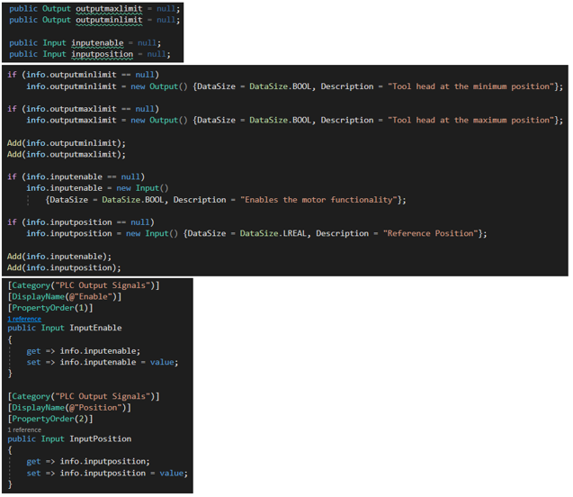
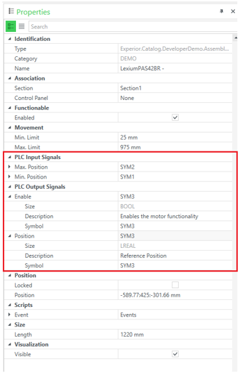
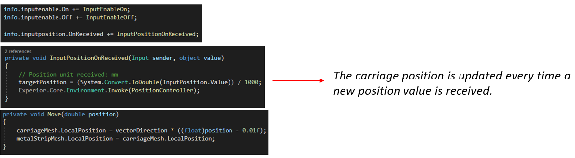
Setting up PLC Inputs and Outputs
To start to program the behavior we need the PLC signals. We create the inputs and outputs and add them to the assembly. Down below is the code added to the component to get the PLC properties interface shown on the right.
Component functionality testing
Now that we have the basic geometry and we have the PLC signals, we can start to program the behavior.
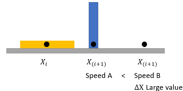
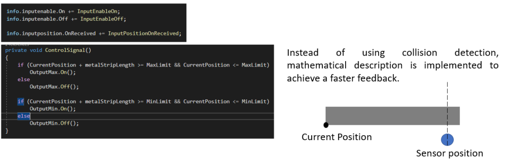
A simple PLC control logic routine was programmed to verify the correct functionality and response of the component under different scenarios based on low and high-speed values.
The logic can be described in the following steps:
1.The carriage moves forward until the maximum limit sensor is collided.
2.Once the sensor returns the feedback to the PLC, the carriage moves backward until the minimum limit sensor is collided.
3.The cycle starts again.
Different approach
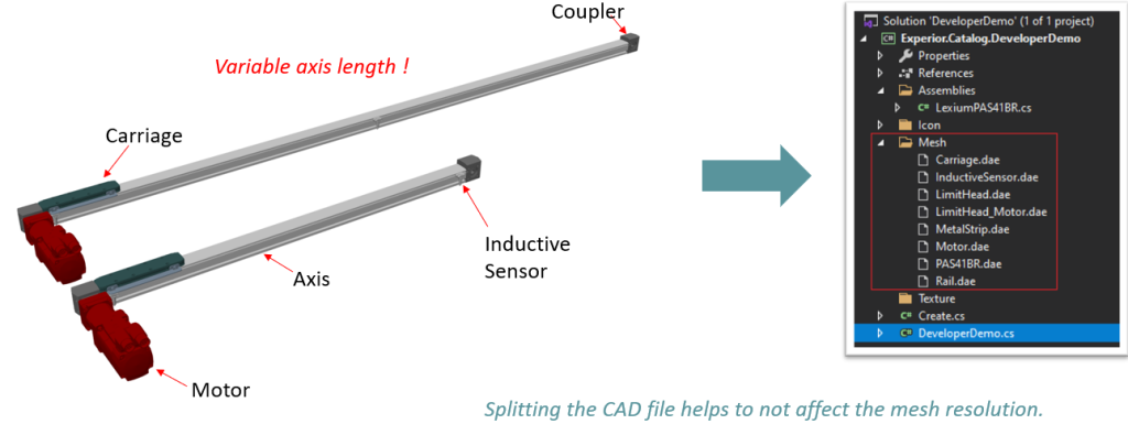
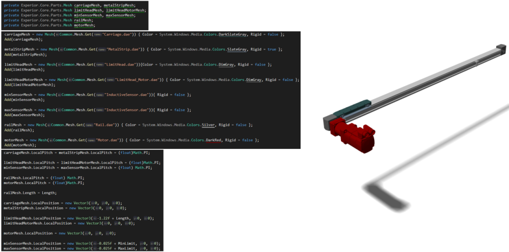
Implementing CAD
When working with a component that has a variable size, we should look at splitting up the original CAD file into smaller parts. This will insure that when we change the length of the metal axis, the mesh of the remaining parts will not be affected. After that, we are ready to add the CAD files to the basic representation from earlier.
The rest of the process is testing each individual part and tweaking whereever necessary.