Diagnostics via the Integrated HMI
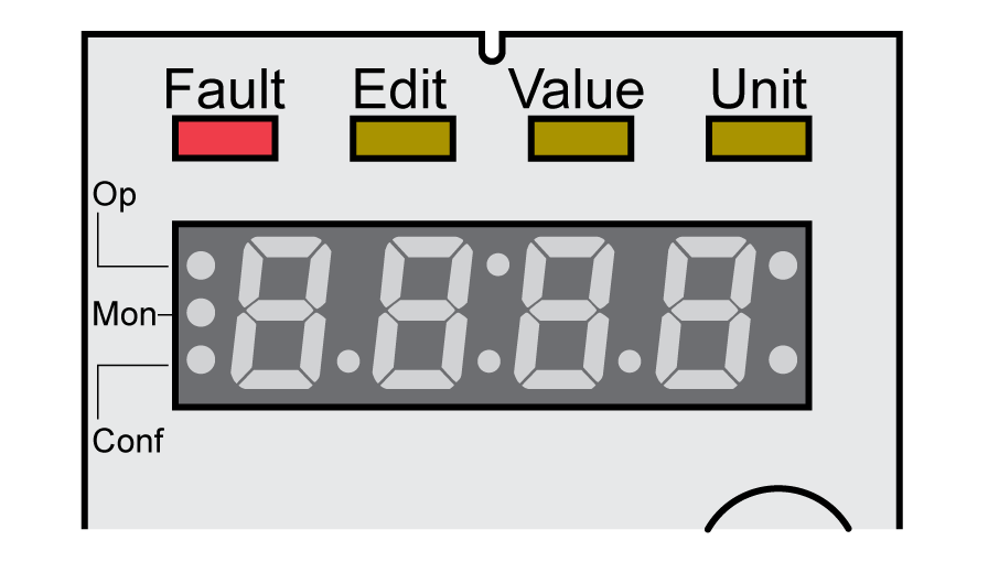
The 7-segment display provides the user with information.

With the factory setting, the 7-segment display shows the operating states. The operating states are described in chapter Operating States.
|
Message |
Description |
|---|---|
|
(INIT) |
Operating state 1 Start |
|
(nrdy) |
Operating state 2 Not Ready To Switch On |
|
(dis) |
Operating state 3 Switch On Disabled |
|
(rdy) |
Operating state 4 Ready To Switch On |
|
(son) |
Operating state 5 Switched On |
|
(run) and (halt) |
Operating state 6 Operation Enabled |
|
(stop) |
Operating state 7 Quick Stop Active |
|
(flt) |
Operating state 8 Fault Reaction Active and 9 Fault |
The table below provides an overview of the messages that can additionally be displayed on the integrated HMI.
|
Message |
Description |
|---|---|
|
(Card) |
Data on the memory card differs from data in the product. See chapter Memory Card for information on how to proceed. |
|
(disp) |
An external HMI is connected. The integrated HMI has no function. |
|
(fsu) |
Perform a First Setup. See chapter Powering on the Device for the First Time. |
|
(mot) |
A new motor was detected. See chapter Acknowledging a Motor Change for replacing a motor. |
|
(prot) |
Parts of the integrated HMI were locked with the parameter HMIlocked. |
|
(slt1) ... (slt2) |
The device has detected a different equipment with modules. See chapter Acknowledging a Module Replacement for replacing modules. |
|
(ulow) |
24 Vdc control supply during initialization not high enough. |
|
(wdog) |
Undeterminable system error. Contact your Schneider Electric service representative. |
|
(8888) |
Undervoltage 24 Vdc control supply. |