In the operating mode Jog, a movement is made from the actual motor position in the specified direction.
A movement can be made using one of two methods:
oContinuous movement
oStep movement
In addition, the product features two parameterizable velocities.
Further, the movement can be made either in a positive or negative direction for both methods:
o( JG-) : slow movement in positive direction
o( JG=) : fast movement in positive direction
o(-JG ) : slow movement in negative direction
o(=JG ) : fast movement in negative direction
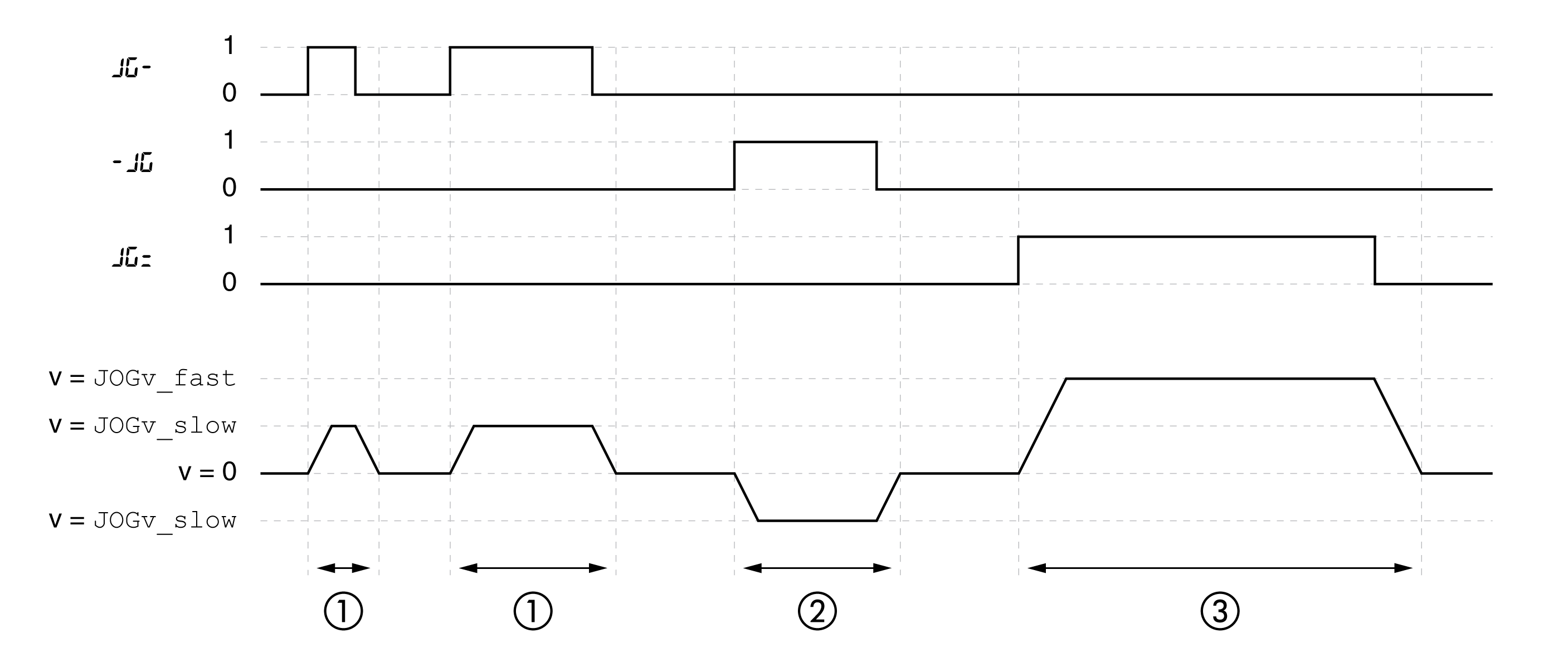
As long as the signal for the direction is available, a continuous movement is made in the desired direction.
The illustration below provides an example of continuous movement:

1 Slow movement in positive direction
2 Slow movement in negative direction
3 Fast movement in positive direction
If the signal for the direction is available for a short period of time, a movement with a parameterizable number of user-defined units is made in the desired direction.
If the signal for the direction is available continuously, a movement with a parameterizable number of user-defined units is made in the desired direction. After this movement, the motor stops for a defined period of time. Then a continuous movement is made in the desired direction.
The illustration provides an example of step movement:

1 Slow movement in positive direction with a parameterizable number of user-defined units JOGstep
2 Waiting time JOGtime
3 Slow continuous movement in positive direction
It is also possible to start the operating mode via the HMI. Calling →(OP)→(jog-)→(JGST) enables the power stage and starts the operating mode.
The method Continuous Movement is controlled via the HMI.
Turn the navigation button to select one of 4 types of movement:
o( JG-) : slow movement in positive direction
o( JG=) : fast movement in positive direction
o(-JG ) : slow movement in negative direction
o(=JG ) : fast movement in negative direction
Press the navigation button to start the movement.
Information on the operating state and the ongoing movement is available via signal outputs.
The table below provides an overview of the signal outputs:
|
Signal output |
Signal output function |
|---|---|
|
DQ0 |
"No Fault" Signals the operating states 4 Ready To Switch On, 5 Switched On and 6 Operation Enabled |
|
DQ1 |
"Active" Signals the operating state 6 Operation Enabled |
|
DQ2 |
"Freely Available" See chapter Setting a Signal Output via Parameter |
It is possible to change the factory settings of the signal outputs, see chapter Digital Inputs and Outputs.