Refer to Diagnostic class (standard): 3
|
Default reaction |
||
|---|---|---|
|
D |
E |
|
|
- |
- |
There is a detected wiring error.
|
Ext. diagnosis |
Meaning |
|---|---|
|
Overload |
The affected output is short circuited or overloaded. For outputs of a Lexium 62, there is no special diagnostic message stating that the supply voltage of the OnBoard I/O modules is not connected. Therefore, when setting an output of a Lexium 62, this diagnostic message Overload is shown. oVerify and correct if necessary the wiring of the output. oOnly for drives: Verify and correct or replace if necessary the wiring of 24 V supply voltage for the OnBoard I/Os. |
NOTE: To use the DIO8 module (optional module of Lexium 62 ILM Module), the following must be taken into account: by PowerSupply = Intern / FALSE this message is assigned to the object of the DIO8 module. An assignment to an output is not possible. If PowerSupply = External / TRUE, then the message is assigned to the relevant output.
|
Ext. diagnosis |
Meaning |
|---|---|
|
Openload |
The output is not connected or only slightly loaded. oVerify and correct if necessary the wiring of the output. oIt may be useful to disable the diagnostic message. (Openload detection is not possible for Lexium 62 and Lexium 62 ILM because it is not supported by hardware.) |
|
PowerFail |
The external power supply of the digital output was not connected. The supply of the digital output is verified if at least one bit is set to 1 in the DiagMask parameter of the output group object. oVerify and correct if necessary the power supply of the digital output. oVerify the DiagMask parameter. |
|
PowerFail (BT-4/ENC1) |
The power supply of the encoder is too low. Parameter EncPowerSupply = Intern / FALSE: Short-circuit of the power supply (pins 5 and 9) of the connected encoder or inoperable bus terminal BT-4/ENC1 Parameter EncPowerSupply = Extern / TRUE: There is no or not enough power at the X5 plug connector or there is a short-circuit of the power supply (pins 5 and 9) of the connected encoder. oVerify and correct if necessary the power supply of the encoder. oVerify and correct or replace if necessary the encoder cable. |
|
PowerFail (BT-4/ENC1) |
A SinCos encoder (physical encoder) was entered in the PLC configuration, but no SinCos encoder is recognized at connector X2 or X3 of BT-4/ENC1. o Plug the SinCos encoder cable into the BT-4/ENC1 X2 or X3 connections. oVerify and correct or replace if necessary the encoder cable. |
|
type not supp. |
The connected encoder type is not supported by the system. Connect an encoder supported by the system. |
|
out <-> out |
Power is supplied externally to the connectors X2, X3, or X4 (pin 5 and 9) of the bus terminal BT-4/ENC1. The connector for the incremental encoder output may have been plugged into an encoder input. Verify and correct if necessary the assignment of the encoder connectors. |
|
IncIn <- IncIn |
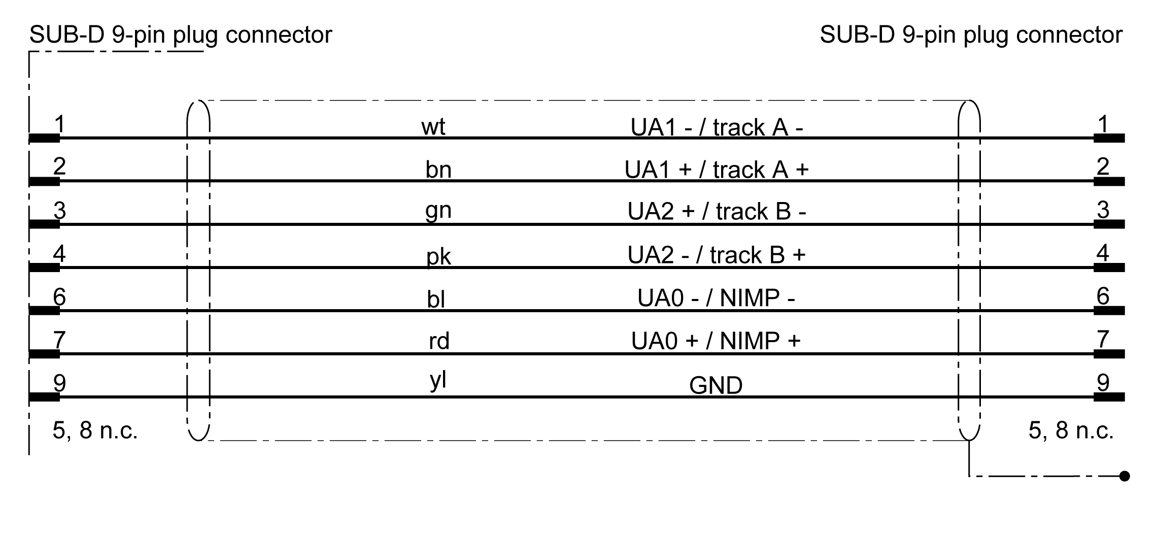
Power is supplied from both sides. oVerify and correct if necessary the wiring. Refer to the section regarding wiring (SUB-D 9-pin plug connector) hereafter. oVerify and replace if necessary the encoder type. Refer to the section regarding supported encoders hereafter. |
NOTE: In certain cases, another diagnostic code or diagnostic class is entered in the message logger of the controller for DIO8 module and Lexium 62 Drive/Lexium 52 Drive onboard I/O modules in the message logger of the drive.
Wiring (SUB-D 9-pin plug connector)

Absolute encoder (single turn/multi turn)
Controller interface characteristics
|
Encoder type |
SINCOS© encoder, Hiperface |
|
Power supply |
9 V / 400 mA (protected against overload) |
|
Diagnosis |
Cable damage, encoder damage |
|
Analog input frequency |
Max. 200 kHz |
|
Analog input signal |
Differential amplifier with high CMRR and HF filter 0.9 V-1.1 V pp 2.2 V-2.8 V offset |
|
Parameter channel |
RS-485, 9600 baud, 8O1 |
|
Cable length |
≤ 50 m tested |
Incremental encoder
Controller interface characteristics
|
Encoder type |
Incremental |
|
Power supply |
5 V / 400 mA (protected against overload) |
|
Diagnosis |
Cable damage, encoder damage |
|
Input frequency |
1 MHz (maximum) |
|
Input signal |
Logic: RS422 standard High: >1.5 V (encoder input) Low: <1.3 V (encoder input) |
|
Impulse multiplication |
* 4, not configurable |
|
Cable length |
≤ 50 m tested |