In the following table, the device reactions are sorted according to their priority (from High to Low).
|
Device reaction |
Diagnostic class |
Subclass |
Meaning |
Diagnostic example |
|---|---|---|---|---|
|
AD |
3 |
6 |
oThe motor is immediately switched to a torque-free state. By default, the brake engages immediately. oThe brake behavior can be changed via the BrakeMode parameter. |
|
|
BD1 |
3 |
5 |
oBest possible stop: drive is stopped with peak current MaxDrivePeakCurrent. oMaxDrivePeakCurrent can be influenced via UserDrivePeakCurrent. An additional limit with UserCurrentLimit is ineffective. oThe brake engages at a speed of rotation of less than 10 rpm. The brake behavior can be changed via the BrakeMode parameter. oThe drive becomes torque free after StopTimeLim + BrakeCouplingTime at the latest. If the speed of rotation is greater than 10 rpm after StopTimeLim (default value: 400 ms), then the diagnostic message 8140 Motor ramp down time exceeded is triggered. |
|
|
BD2 |
3 |
4 |
oStandstill after user default (user-defined stop). The drive is brought to a standstill with the delay ControllerStopDec and the jerk ControllerStopJerk. oThe current is limited with the peak current MaxDrivePeakCurrent. MaxDrivePeakCurrent can be influenced via UserDrivePeakCurrent. An additional limit with UserCurrentLimit is ineffective oThe actual values (standard) or reference values are used as start values for the stop profile depending on the UserDefinedStopMode parameter. oThe brake engages at a speed of rotation of less than 10 rpm. oThe drive becomes torque free after StopTimeLim + BrakeCouplingTime at the latest. oIf the speed of rotation is greater than 10 rpm after StopTimeLim (default value: 400 ms), then the diagnostic message 8140 Motor ramp down time exceeded is triggered. |
|
|
CD |
3 |
3 |
oStandstill due to specified reference value. oThe axis must be shut down by the application program. This has to be done by a user-defined motion profile. The standstill has to be reached at the latest after StopTimeLim (default value: 400 ms) and ControllerEnable must be disabled. Otherwise the diagnostic message 8140 Motor ramp down time exceeded is triggered. |
For this device reaction there is no diagnostic message defined by default. |
|
D |
2 |
2 |
Informing message to PacDrive LMC. The program can be used for controlled, synchronous shutdown. If the PacDrive LMC does not trigger a reaction in the drive a diagnostic message with the device reaction AD, BD1, BD2, or CD may occur. |
|
|
E |
1 |
1 |
Message |
The device reaction can be reconfigured by using the function FC_DiagConfigSet2 or FC_DiagConfigSubClassGroupSet. The priority of the configured device reaction must always be equal to or greater than the priority of the minimum device reaction. The minimum device reactions are indicated in the respective diagnostic message or in the overview table.
The above-mentioned device reactions are also triggered by the following events:
oIf ControllerEnable is set to FALSE and the AxisState is > 2, device reaction BD2 is triggered by default. The reaction can be changed by using the ControllerEnableStopMode parameter.
oIf TorqueEnable is set to FALSE and the AxisState is > 2, the device reaction AD is triggered.
In the event of reaction BD2, you can decide whether the defined shutdown profile starts with actual or reference values. In the PacDrive system, the term "actual" refers to real time, real world measured values. The term "reference" refers to values that are derived or otherwise calculated. By default, the profile is started with actual values:
|
Starting with actual values |
oDetected tracking errors are considered in the shutdown profile. oIf the reaction is triggered by the drive colliding with an obstacle, the approach of a position which is located behind the obstacle is avoided as a result. oSince no permissible value is available in the drive for the actual acceleration, the start acceleration is performed with zero. oIf the actual values differ from the reference values, a jump occurs at the reference velocity and the reference position. |
|
Starting with reference values |
oNo jumps occur in the reference value profile. oThis mode is useful to achieve a coordinated ramp down of several drives. The reference value can be located behind an obstacle. The drive will attempt to approach the target position. In case it gets blocked before reaching the target position the current is limited to the peak current MaxDrivePeakCurrent. oIf the drive is slowed down by the obstacle, the drive attempts to move along the requested reference value profile with MaxDrivePeakCurrent. oIf the drive has been additionally limited with UserCurrentLimit before the reaction, the drive presumably accelerates until the tracking error is corrected. |
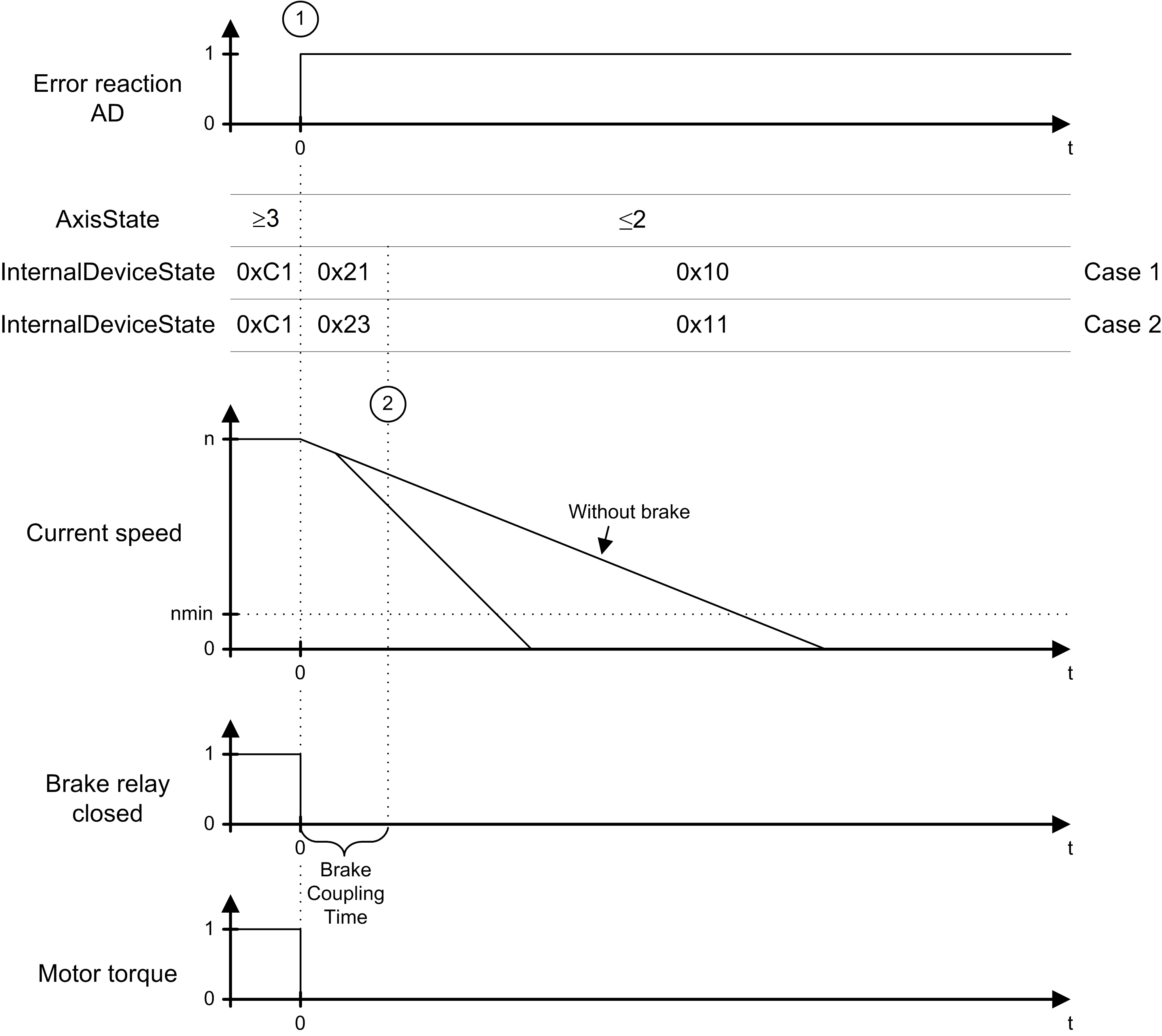
In the case of an error detected with the reaction AD (Drive) (1), the axis is switched torque-free immediately and the brake relay is released. The axis behavior depends on whether the motor is equipped with a holding brake or not.
Upon expiration of the BrakeCouplingTime, the axis is in the error state 0x10 or 0x11. To return from these states to a controlled state the diagnostic message has to be acknowledged and the axis has to come to a standstill.
The graphic shows the time diagram for reaction AD:

Time Diagram for Reactions BD1 / BD2
In case of a diagnostic message with reaction BD1 or BD2, two sequences can occur:
oRamping Down Within the Maximum Ramp-Down time
oMaximum Ramp-Down time Exceeded
Ramping Down Within the Maximum Ramp-Down time
|
If... |
Then... |
|---|---|
|
An error is detected with reaction BD1 (1) |
The axis ramps down at maximum current (MaxDrivePeakCurrent). |
|
An error detected with reaction BD2 (1), |
The axis ramps down according to the parameter ControllerStopDec and ControllerStopJerk. |
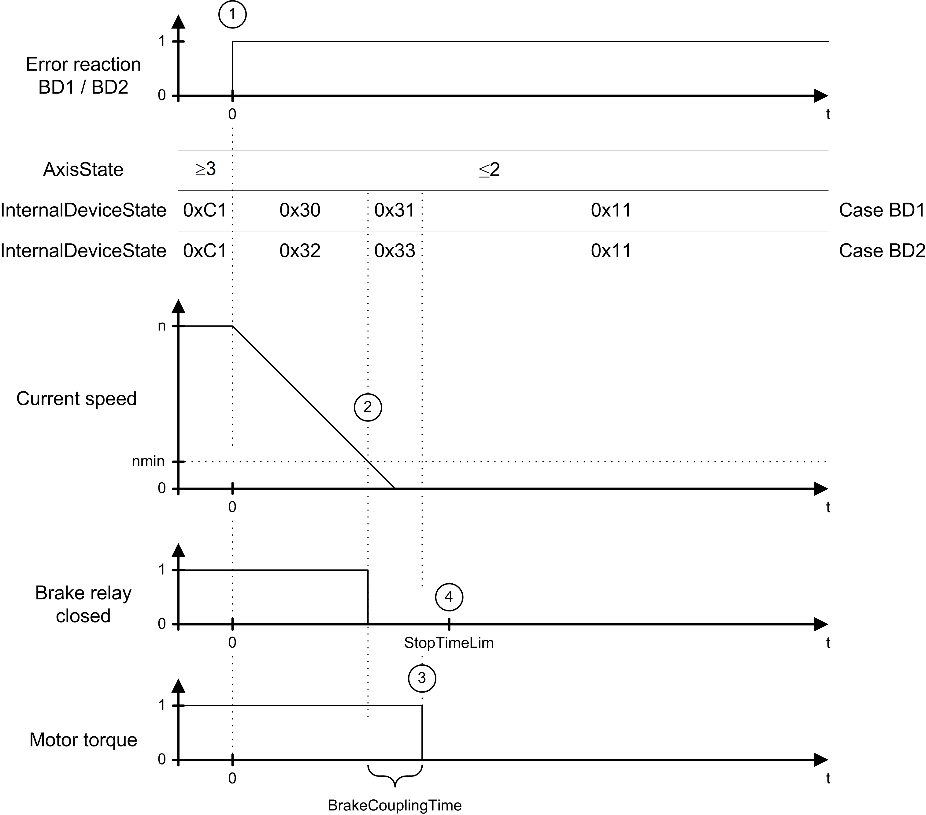
As soon as the actual speed becomes lower than the speed threshold (actual speed < nmin) (2), the brake relay is switched to couple the brake.
The axis comes to a standstill before expiration of the maximum ramp-down time (parameter StopTimeLim) (4). After expiration of the brake coupling time (parameter BrakeCouplingTime) (3), the motor is switched to a torque-free state.
The graphic shows the time diagram for reaction BD1 / BD2 (ramping down within the max. ramp down time):

Maximum Ramp-Down time Exceeded
|
If... |
Then... |
|---|---|
|
An error is detected with reaction BD1 (1). |
The axis ramps down at maximum current (MaxDrivePeakCurrent). |
|
An error is detected with reaction BD2 (1). |
The axis ramps down according to the parameter ControllerStopDec and ControllerStopJerk. |
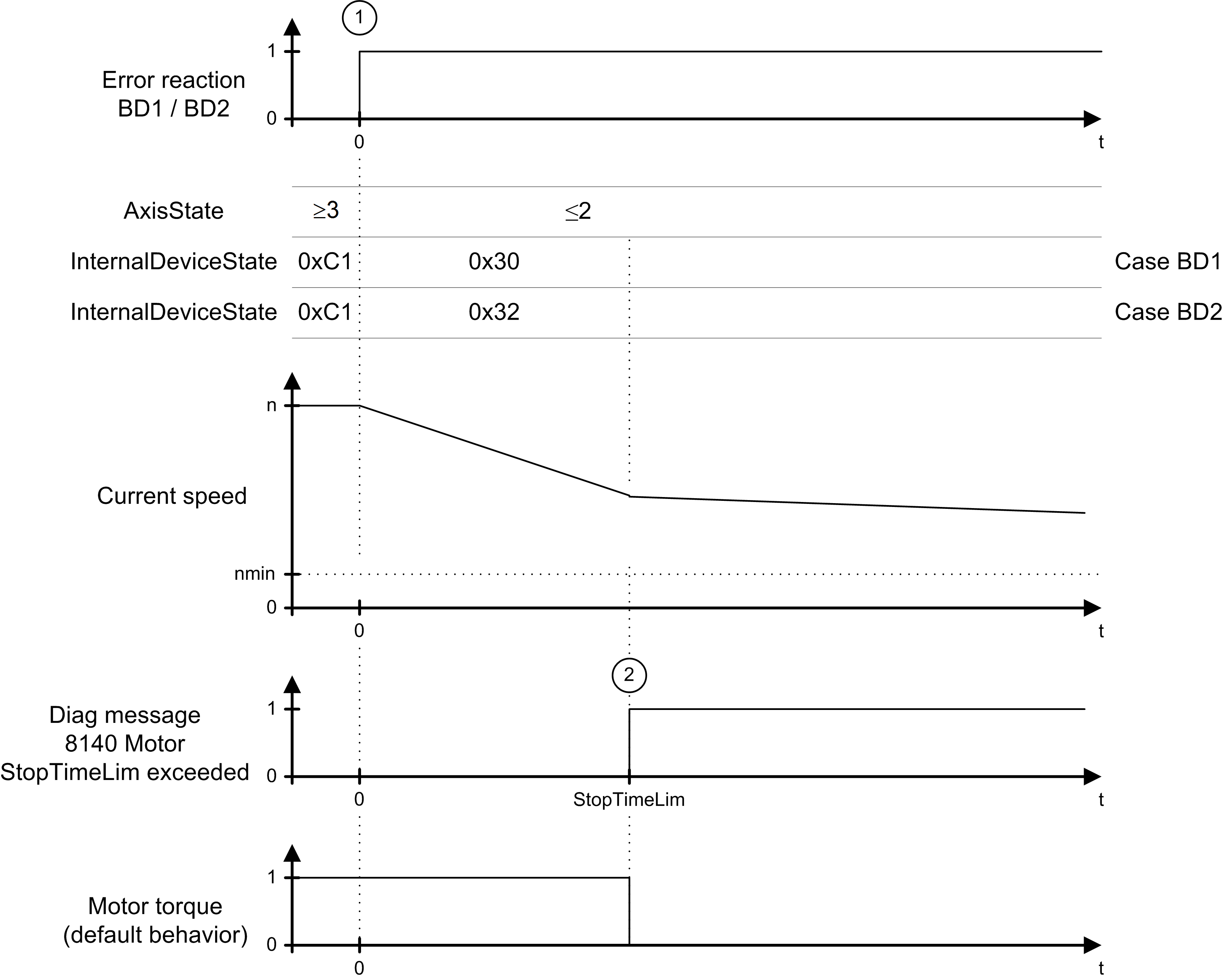
The axis does not come to a standstill before expiration of the maximum ramp-down time (parameter StopTimeLim) (2) (actual speed < nmin). Therefore, error message 8140 Motor ramp-down time exceeded is triggered.
The graphic shows the time diagram for reaction BD1 / BD2 (maximum ramp down time exceeded):
