The installation fasteners are required when installing the panel.
Mount the panel in an enclosure that provides a clean, dry, robust, and controlled environment:
oHMIGTO (except HMIGTO2315 / HMIGTO5315 / HMIGTO6315): IP65, Type 1, Type 4X [Indoor Use Only] or Type 13 enclosure.
oHMIGTO2315 / HMIGTO5315 / HMIGTO6315: IP66k, Type 1, Type 4X [Indoor Use Only] or Type 13 enclosure.
|
Check that the installation wall or cabinet’s surface is flat, in good condition and has no jagged edges. Metal reinforcing strips may be attached to the inside of the wall, near the panel-cut, to increase its rigidity. |
|
Decide on the thickness of the enclosure wall, based on the level of strength required: 1.6...5 mm (0.06...0.2 in.). |
|
Be sure that the surrounding air temperature and the ambient humidity are within their designated ranges. Surrounding air temperature: 0...50 °C (32...122 °F) or 0...55 °C (32...131 °F) (see the Environment Specifications for your HMIGTO); ambient humidity: 10...90% RH; wet bulb temperature: maximum 39 °C [102 °F]. When installing the panel in a cabinet or enclosure, the surrounding air temperature is the cabinet's or enclosure's internal temperature. 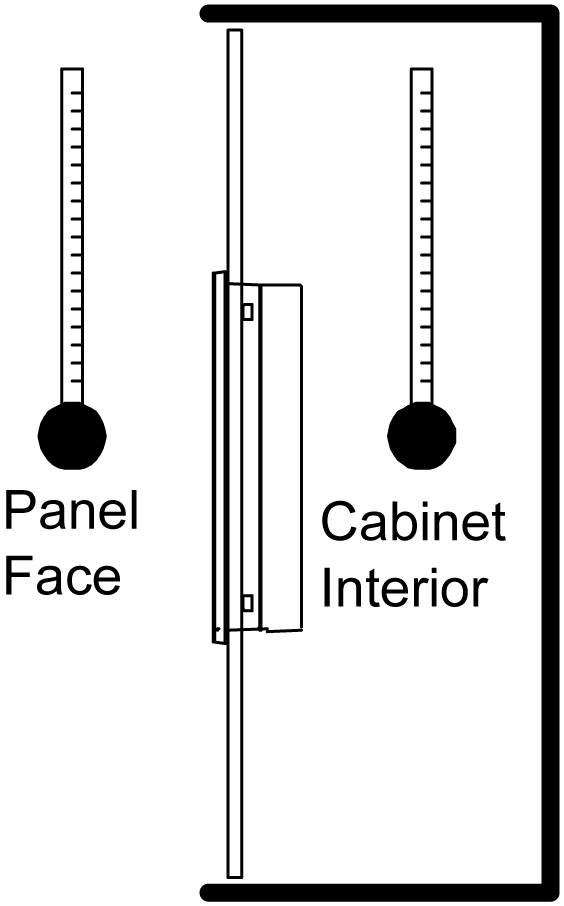
|
|
Be sure that heat from surrounding equipment does not cause the panel to exceed its standard operating temperature. |
|
When mounting the panel vertically, ensure that the right side of the unit faces up. In other words, the power connector should be at the top. 
1 Power connector |
|
When installing the panel in a slanted position, the panel face should not incline more than 30°. 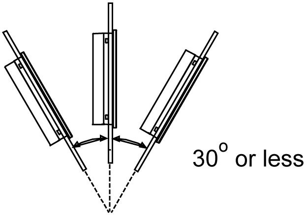
|
|
When installing the panel in a slanted position with an incline more than 30°, the ambient temperature must not exceed 40 °C (104 °F). You may need to use forced air cooling (fan, A/C) to ensure that the ambient operating temperature is 40 °C or less (104 °F or less). |
|
For easier maintenance, operation and improved ventilation, install the panel at least 100 mm (3.94 in.) away from adjacent structures and other equipment as shown in the following illustration: 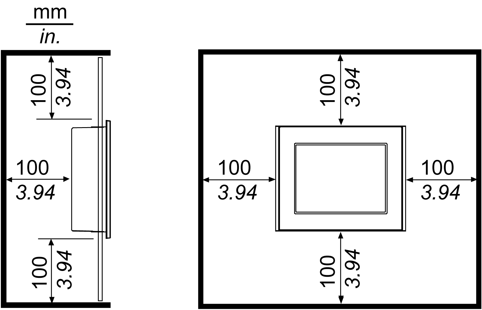
|
|
The holes on the rear of the panel (except HMIGTO1300/1310) do not correspond to VESA 75 mm standards. Do not attach the panel to a commercial-type VESA arm. |
Panel Mounting Procedure: : (Except HMIGTO2315/HMIGTO5315/HMIGTO6315)
|
Step |
Action |
|---|---|
|
1 |
Place the panel on a clean and level surface with the display facing downward. |
|
2 |
Check that the panel's gasket is seated securely into the gasket's groove, which runs around the perimeter of the panel frame. |
|
3 |
Cut a hole in the installation panel as defined by the HMIGTO's panel cutout dimensions. |
|
4 |
Insert the HMIGTO into the panel-cut. |
|
5 |
Insert the installation fasteners into the HMIGTO's insertion slots on the top and bottom sides (left and right sides for the HMIGTO1300/1310). Slide the fasteners to the back. If the fasteners are not correctly attached, the HMIGTO may shift or fall out. 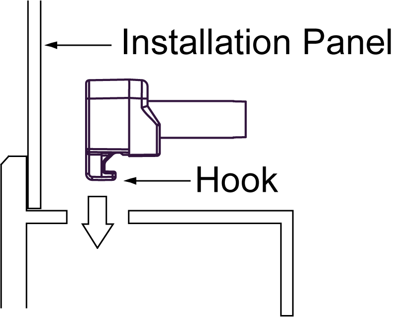
HMIGTO2310 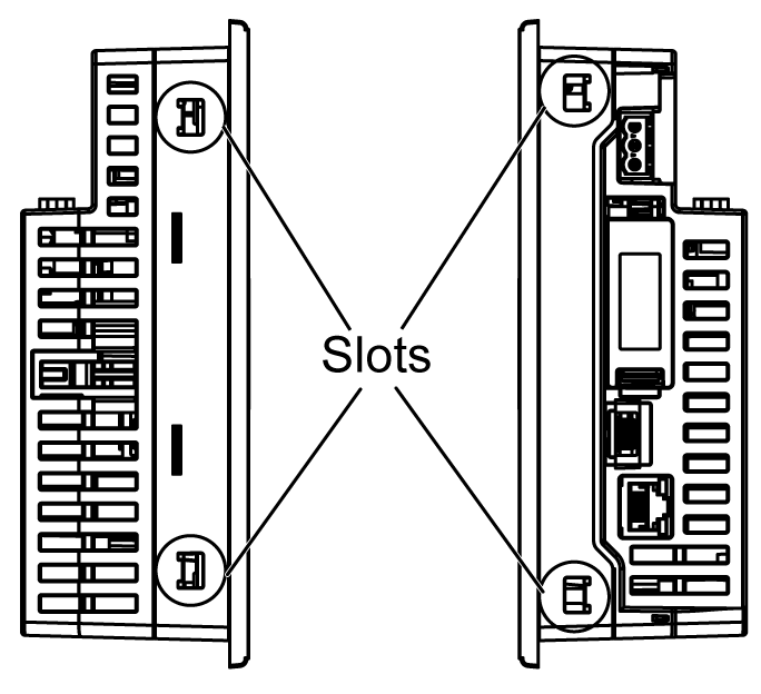
HMIGTO1310 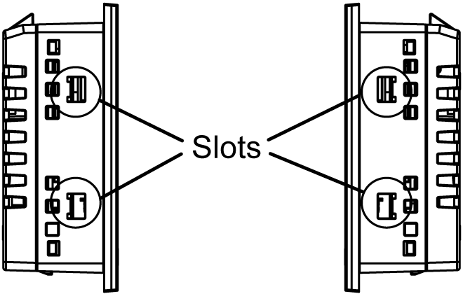
|
|
6 |
Insert each of the fasteners shown below. Make sure that you pull the fastener back until it is flush with the rear of the attachment hole insert. 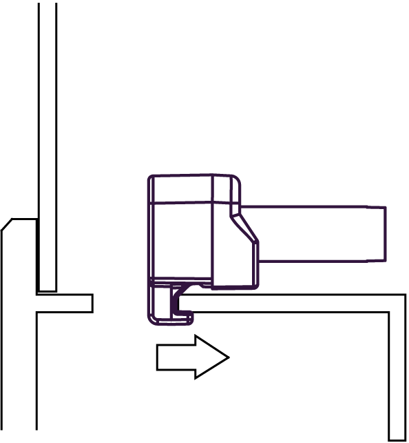
|
|
7 |
Use a Phillips screwdriver to tighten each fastener screw and secure the panel in place. The necessary torque is 0.5 Nm (4.4 lb•in). 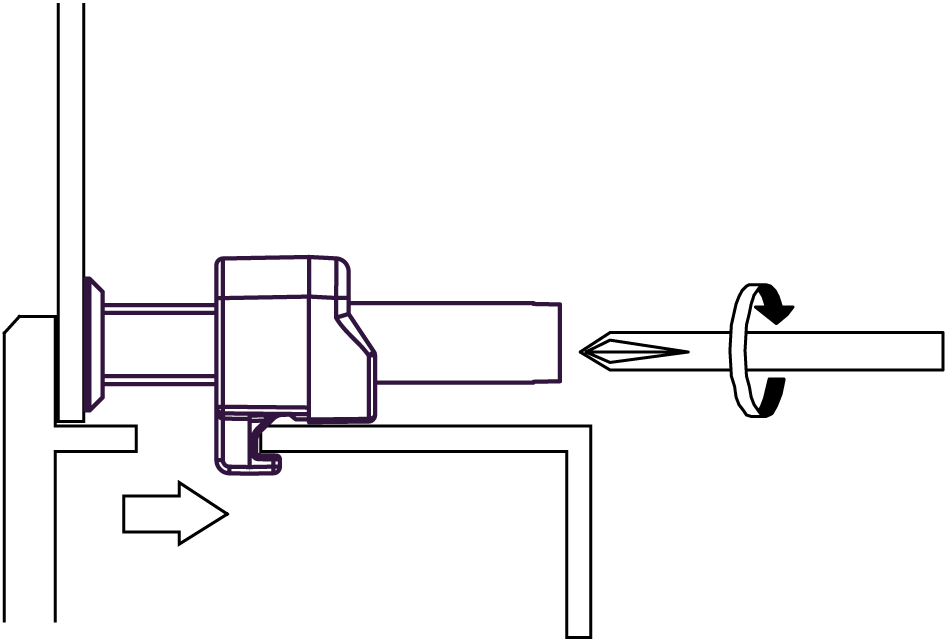
|
Removal Procedure: (Except HMIGTO2315/HMIGTO5315/HMIGTO6315)
|
Step |
Action |
|---|---|
|
1 |
Loosen the installation fasteners (4) from the HMIGTO. |
|
2 |
Remove the HMIGTO slowly from the panel while pressing the projections on the top of the HMIGTO. 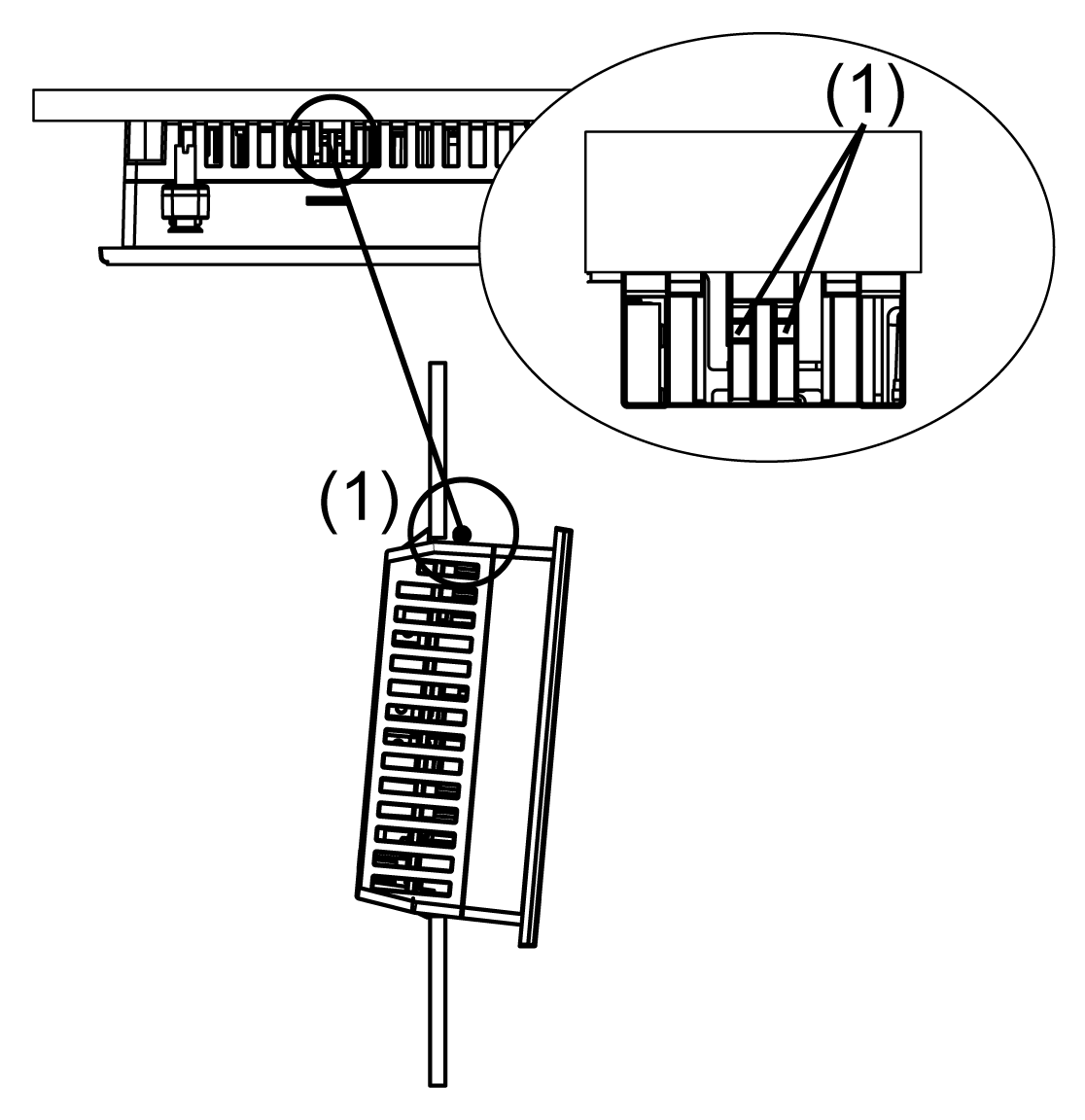
1 Projections NOTE: oYou could damage the HMIGTO if you try to remove it without holding down the projections. oWatch your fingers so they do not get caught when holding down the projections. |
HMIGTO2315/HMIGTO5315/HMIGTO6315 Panel Mounting Procedure
|
Step |
Action |
|---|---|
|
1 |
Place the panel on a clean and level surface with the display facing downward. |
|
2 |
Confirm that the panel's gasket is seated properly on the rear of the panel. |
|
3 |
Cut a hole in the panel as defined by the HMIGTO panel cutout dimensions. |
|
4 |
Insert the HMIGTO into the panel-cut. 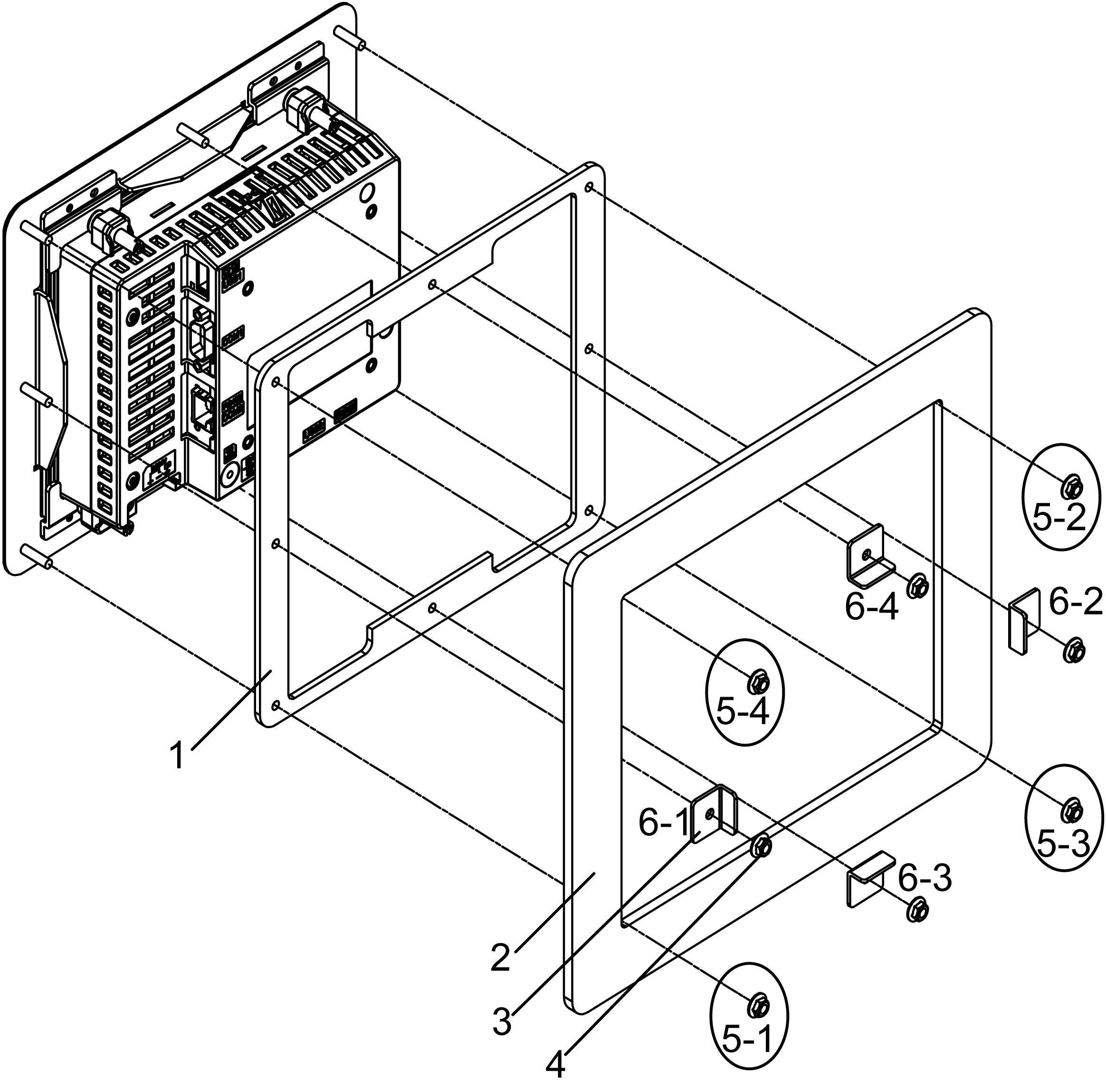
1 Gasket 2 Panel 3 Brackets 4 M4 hex nut 5 Read step 5. 6 Read step 6. |
|
5 |
Tighten the four corners of the rear of the panel with the M4 Hex nuts, in the order shown in the example in Step 4. Use an M4 box-type screwdriver to tighten each M4 Hex nut and secure the panel in place. The necessary torque is 0.5 Nm (4.4 lb•in). If the M4 Hex nuts are not correctly attached, the panel may shift or fall out. |
|
6 |
Attach the bracket onto the screws in the middle between the M4 Hex nuts in the order shown in the example in Step 4. Use an M4 box-type screwdriver to tighten each M4 Hex nut and secure the panel in place. The necessary torque is 0.5 Nm (4.4 lb•in). If the M4 Hex nuts are not correctly attached, the panel may shift or fall out. |
|
7 |
Tighten all the M4 Hex nuts again. The necessary torque is 0.5 Nm (4.4 lb•in). NOTE: Do not loosen the installation fasteners, marked with red squares below. 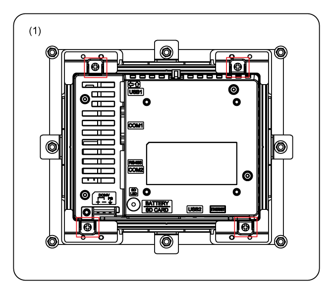
1 Panel |