|
Part
|
Name
|
Description
|
|
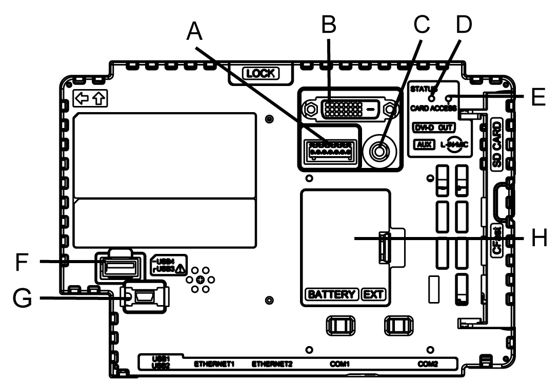
A
|
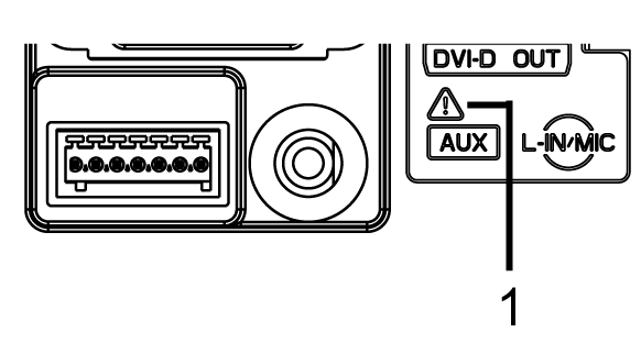
Auxiliary Output/Speaker Output Interface (AUX)
|
This interface is Alarm Output or Buzzer Output, and Sound Output.
1 This mark identifies safety messages and notes about the AUX Connector.
|
|
B
|
DVI-D Output Interface
|
DVI-D Output Interface
|
|
C
|
AUDIO Input Interface
(L-IN/MIC)
|
This interface connects a microphone. Use for mini jack connector (Æ3.5 mm [0.14 in]).
|
|
D
|
Status LED
|
|
|
E
|
Card Access LED
|
|
|
F
|
USB (Type A) Interface
|
Conforms to USB2.0 (Type A) x 1.
Power supply voltage: 5 Vdc ±5%
Maximum current supplied: 500 mA
Maximum transmission distance: 5 m (16.4 ft)
|
|
G
|
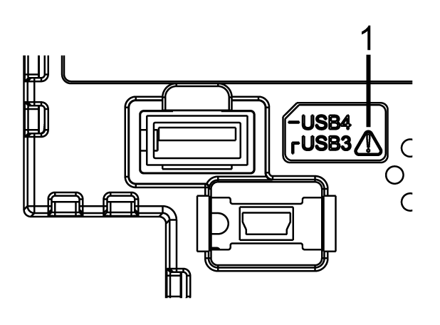
USB (mini-B) Interface
|
Conforms to USB2.0 (mini-B) x 1.
Maximum transmission distance: 5 m (16.4 ft)
1 This mark identifies safety messages about the Interface Connection.
|
|
H
|
Expansion Unit Interface Cover (EXT)
|
The Expansion Unit can be embedded in the Expansion Unit Interface Cover opening, and Battery for Memory Backup can be connected or replaced.
|
|
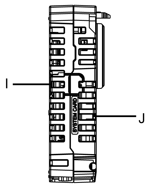
I
|
Storage Card Cover
|
The SD and CFast Card are located in the Storage Card Cover opening.
|
|
J
|
System Card Cover
|
The system card is located in the System Card Cover opening. Do not open this cover when the Box Module is in operation.
|
|
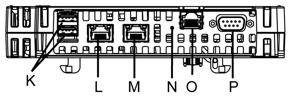
K
|
USB (Type A) Interface
|
Conforms to USB2.0 (Type A) x 2.
Power supply voltage: 5 Vdc ±5%
Maximum current supplied: 500 mA
Maximum transmission distance: 5 m (16.4 ft)
|
|
L
|
Ethernet Interface (Ethernet1)
|
Ethernet transmission interface (10BASE-T/ 100BASE-TX/ 1000BASE-T)
Connector: Modular jack (RJ-45) x 1
|
|
M
|
Ethernet Interface (Ethernet2)
|
Ethernet transmission interface (10BASE-T/ 100BASE-TX/ 1000BASE-T)
Connector: Modular jack (RJ-45) x 1
|
|
N
|
COM1 LED
|
|
|
O
|
Serial Interface (COM1)
|
RS-485 (Isolation) Serial Interface.
Connector: Modular jack (RJ-45) x 1
|
|
P
|
Serial Interface (COM2)
|
RS-232C/422/485 Serial Interface (you can switch the communication method via software).
Connector: D-Sub 9 pin (plug) x 1
|
|
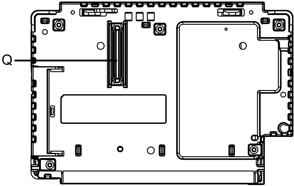
Q
|
Display Module Interface
|
Interface that connects the Display Module and Box Module.
|