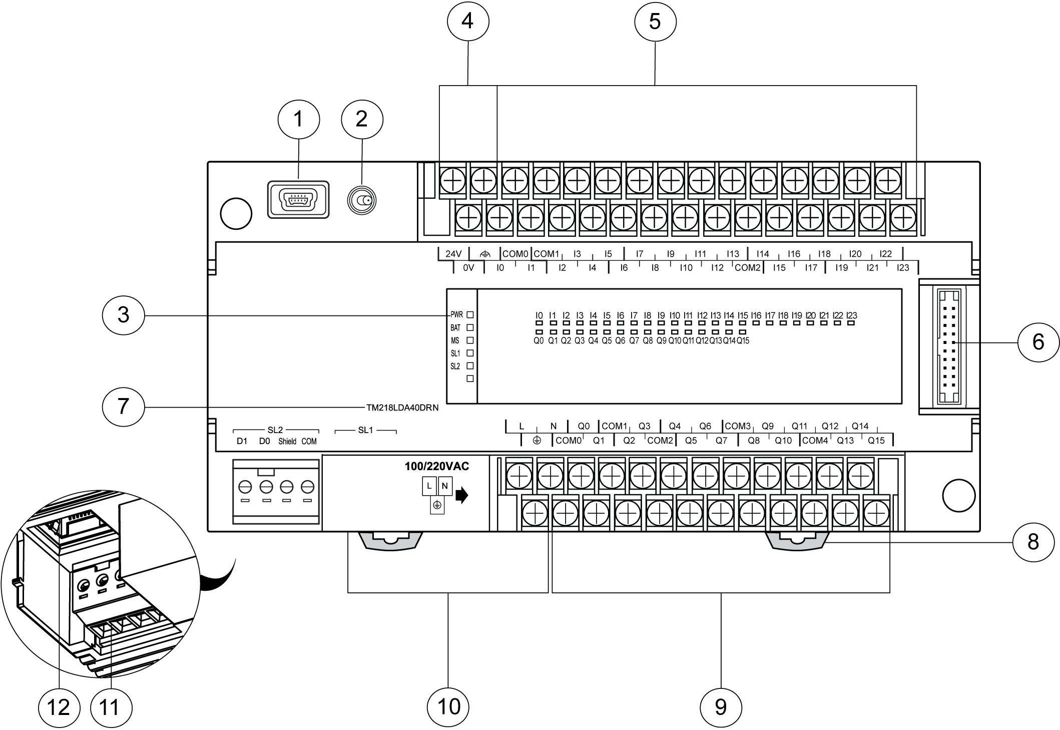
The following illustration shows the different components of the TM218LDA40DRN controller:
|
N° |
Description |
|---|---|
|
1 |
|
|
2 |
|
|
3 |
|
|
4 |
24 V sensor power supply terminal block |
|
5 |
|
|
6 |
Ribbon cable connector |
|
7 |
Reference number |
|
8 |
DIN rail clip |
|
9 |
|
|
10 |
100...220 Vac power supply terminal block and label |
|
11 |
|
|
12 |
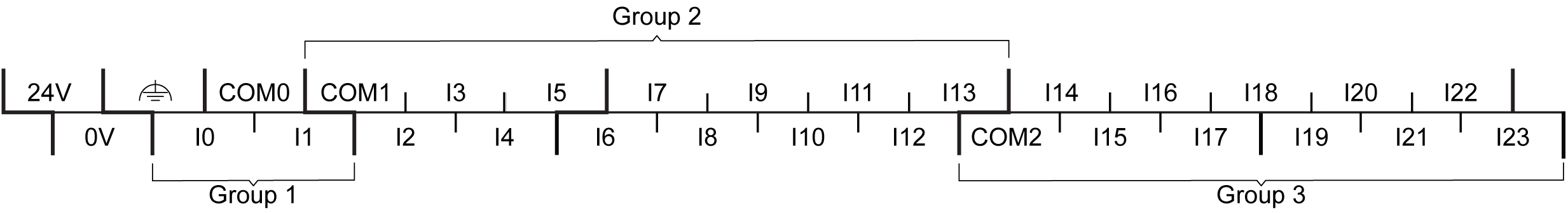
The illustration below shows the pin assignment of the input terminal block:
The illustration below shows the pin assignment of the output terminal block:
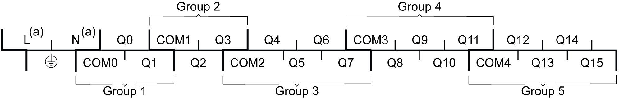
(a) 100...220 Vac power supply terminals are located in the output terminal block. For more information, refer to the topic Power Supply Wiring and Characteristics.
|
|
|
HAZARD OF ELECTRIC SHOCK, EXPLOSION OR ARC FLASH |
|
oDisconnect all power from all equipment including connected devices prior to removing any covers or doors, or installing or removing any accessories, hardware, cables, or wires except under the specific conditions specified in the appropriate hardware guide for this equipment. oAlways use a properly rated voltage sensing device to confirm the power is off where and when indicated. oReplace and secure all covers, accessories, hardware, cables, and wires and confirm that a proper ground connection exists before applying power to the unit. oUse only the specified voltage when operating this equipment and any associated products. |
|
Failure to follow these instructions will result in death or serious injury. |
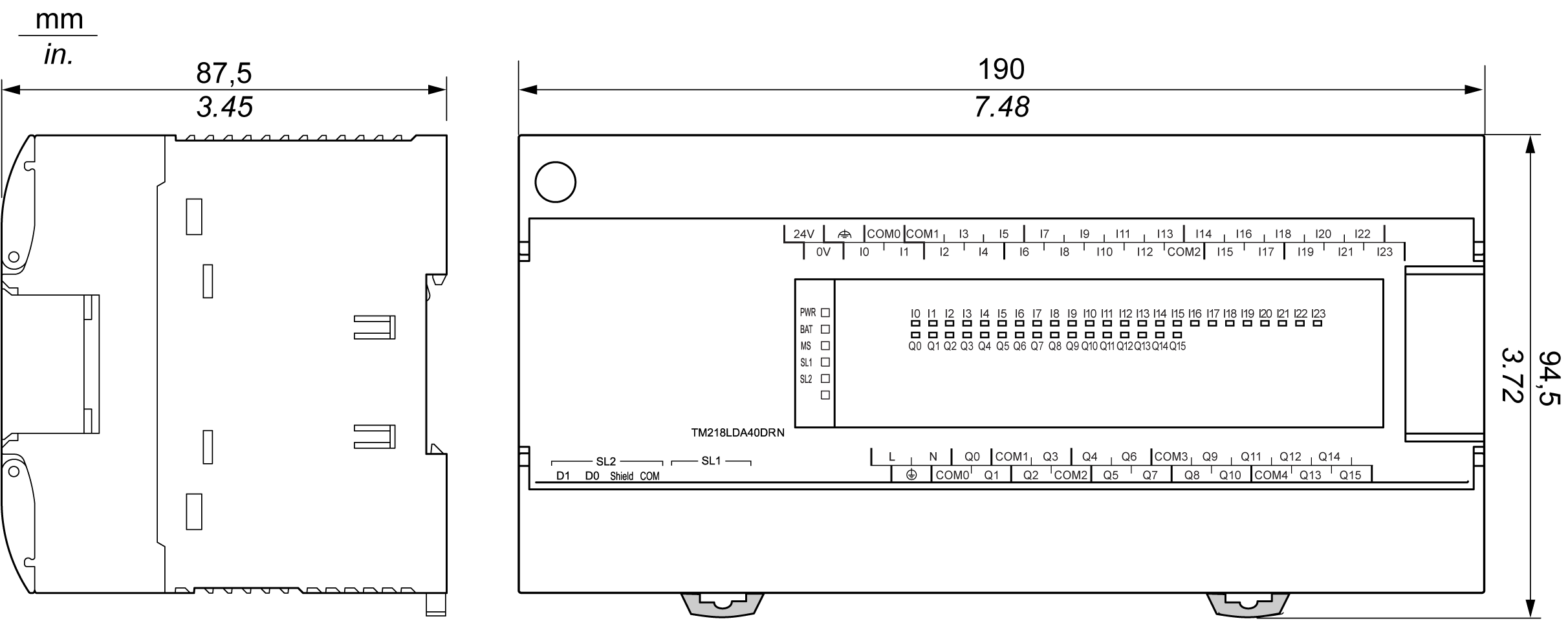
The following illustration shows the external dimensions of the TM218LDA40DRN controller: