The Web server integrated in the TM3 bus coupler offers an easy access using a web browser to the information such as configuration of the most common settings, status, I/O data, Network statistic, and diagnostic info.
The Web server is accessible through the bus coupler USB port and Ethernet port by specifying the IP address or hostname in the address bar. You can use the pages of the website for setup and control as well as application diagnostics and monitoring. These pages are ready to use with a Web browser. No configuration or programming is required.
Any PC providing a USB (host) port and/or an Ethernet interface can connect to the Web server by using a Web browser.
The Web server can be accessed by the web browsers listed below:
oMicrosoft Internet Explorer (version ≥ 11)
oGoogle Chrome (version ≥ 71)
oMozilla Firefox (version ≥ 64)
oMicrosoft Edge (version ≥ 42)
The Web server allows you to monitor a bus coupler and its application remotely, to perform various maintenance activities including modifications to data and configuration parameters. Care must be taken to ensure that the immediate physical environment of the machine and process is in a state that will not present safety risks to people or property before exercising control remotely.
|
|
|
UNINTENDED EQUIPMENT OPERATION |
|
oDefine a secure password for the Web server, and do not allow unauthorized or otherwise unqualified personnel to use this feature. oEnsure that there is a local, competent, and qualified observer present when operating on the controller from a remote location. oYou must have a complete understanding of the application and the machine/process it is controlling before attempting to adjust data, stopping an application that is operating, or starting the controller remotely. oTake the precautions necessary to assure that you are operating on the intended controller by having clear, identifying documentation within the controller application and its remote connection. |
|
Failure to follow these instructions can result in death, serious injury, or equipment damage. |
NOTE: The Web server must only be used by authorized and qualified personnel. A qualified person is one who has the skills and knowledge related to the construction and operation of the machine and the process controlled by the application and its installation, and has received safety training to recognize and avoid the hazards involved. No responsibility is assumed by Schneider Electric for any consequences arising out of the use of this feature.
You can manage the user accounts on the Web server on MAINTENANCE / User Accounts.
By default, the user name is Administrator, and the password is Administrator. You must change the password at the first login.
|
|
|
UNAUTHORIZED DATA ACCESS |
|
oSecure access to the Web server using User Rights. oIf you do not enable User Rights, disable the Web server to prevent any unwanted or unauthorized access to data in your application. |
|
Failure to follow these instructions can result in death, serious injury, or equipment damage. |
|
Step |
Action |
|---|---|
|
1 |
Connect to the bus coupler using the USB port. |
|
2 |
Open the browser. |
|
3 |
Enter the IP address 90.0.0.1. |
|
4 |
Click Reset. |
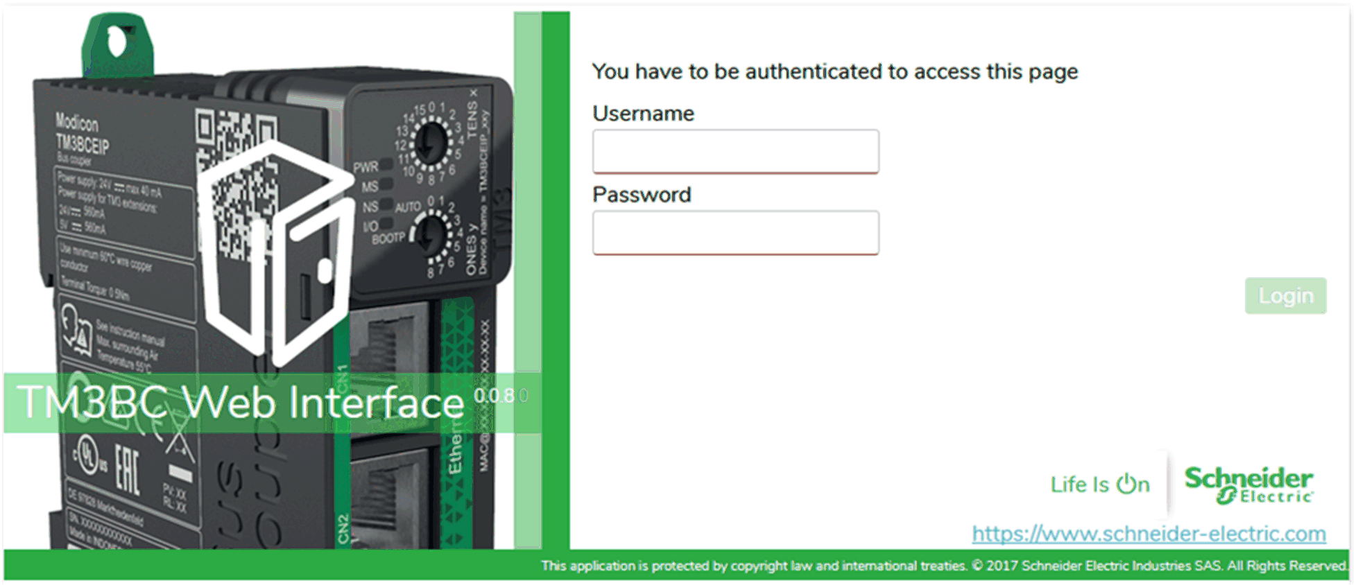
The login page is the entry point to get authenticated by the Web server. To access the website login page shown in the following illustration, type in your navigator the IP address of the TM3 bus coupler or IP address 90.0.0.1 if you are connected by USB. To login to the Web server, enter the user name and password and click Login.

The Web server contains the following pages:
oHOME
NOTE: The timeout session for each login is five minutes. When you do not perform any action after you logged in, it redirects you to the login page if you click any button. You need to log in again with user name and password to access the web pages.
The HOME page shows the product details of TM3 bus coupler.
The identification section of HOME page consists of:
|
Element |
Description |
|---|---|
|
Identification |
|
|
Vendor ID |
Vendor ID of the bus coupler |
|
Vendor Name |
Vendor name of the bus coupler |
|
Product ID |
Product ID of the bus coupler |
|
Product Name |
Product name of the bus coupler |
|
Product Reference |
Product reference of the bus coupler |
|
Serial Number |
Serial number of the bus coupler |
|
Locate Device |
Click the button to locate the bus coupler. The LEDs of the bus coupler flash red for few seconds. |
The DIAGNOSTICS page shows the status of the bus coupler.
The DIAGNOSTICS page contains the following sub-pages:
The Device sub-page shows the details about identification and status of the bus coupler:
|
Element |
Description |
|---|---|
|
Status |
|
|
Last Stop Cause |
Displays the cause of the last stop of the bus coupler. |
|
USB Port |
Displays whether a USB cable is connected to the bus coupler. |
|
Operating Mode |
Displays one of the following operating modes of the bus coupler: oIdle oRun |
|
Configuration Status |
Displays one of the following configuration status of the bus coupler: oNot Configured oConfigured |
The Ethernet sub-page shows the configuration and status of Ethernet connection:
|
Element |
Description |
|---|---|
|
Configuration |
|
|
MAC Address |
MAC address of the bus coupler. |
|
Mode |
Displays the IP mode of the bus coupler: oDHCP oManual |
|
IP Address |
IP address of the bus coupler |
|
Subnet Mask |
Subnet mask of the bus coupler |
|
Gateway Address |
Gateway address of the bus coupler |
|
Statistics |
|
|
TX Bytes |
Displays the number of the bytes transmitted. |
|
ErroneousTXFrames |
Displays the number of the frames transmitted in error. |
|
Rx Bytes |
Displays the number of the bytes received. |
|
ErroneousRXFrames |
Displays the number of the frames received in error. |
|
Refresh |
Refreshes the values. |
|
Connections |
Displays the number of the configured connections of the bus coupler. |
|
TX Frames |
Displays the number of frames transmitted. |
|
RX Frames |
Displays the number of frames received. |
|
Reset |
Resets the values to zero. |
The Ethernet/IP sub-page shows the status information of Ethernet/IP:
|
Element |
Description |
|---|---|
|
Refresh |
Refreshes the values. |
|
Statistics |
|
|
TX I/O Messages |
Displays the number of I/O messages transmitted through Ethernet/IP. |
|
RX I/O Messages |
Displays the number of I/O messages received through Ethernet/IP. |
|
Failed TX I/O Messages |
Displays the number of erroneous I/O messages that were not transmitted through Ethernet/IP. |
|
Failed RX I/O Messages |
Displays the number of erroneous I/O messages that were not received through Ethernet/IP. |
|
UCMM Requests |
Displays the number of UCMM requests. |
|
Reset |
Resets all the values to zero. |
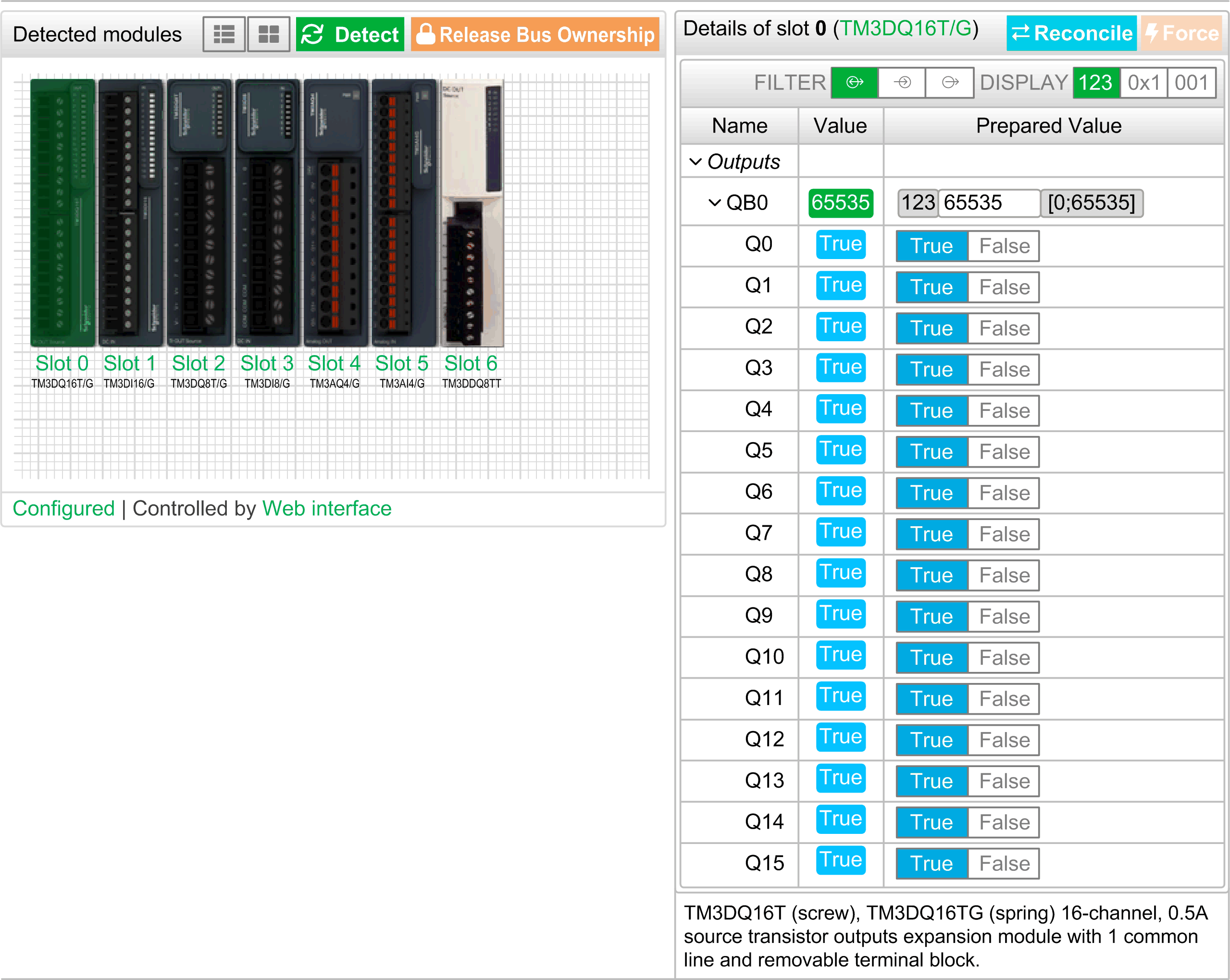
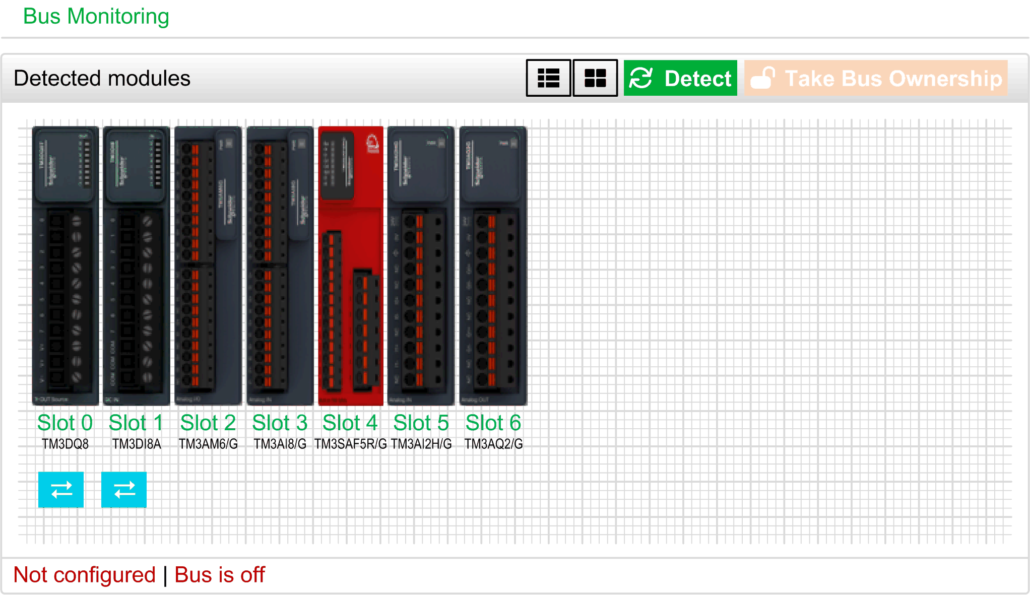
The MONITORING page displays the TM2 and TM3 expansion modules that are connected to the TM3 bus coupler.
The following illustration shows MONITORING page:

The following illustration shows MONITORING page with values:

The following illustration shows MONITORING page without values:

This page shows and describes all the modules detected by the bus coupler and allows you to:
oSee the state of a module (running or not running) and the protocol used.
oRead the value of an input or output.
oForce a value to an output.
|
Element |
Description |
|---|---|
|
List view |
Shows the detected modules in a list. Click the module to select it. Click the up and down arrows to sort the modules. |
|
Graphic view |
Shows the detected modules in respect of their physical order. Click the module to select it. |
|
Detect |
Allows you to detect the modules connected to the bus coupler. |
|
Take Bus Ownership Release Bus Ownership |
Reserves the bus to allow you to force the module outputs. You can click the button when the bus coupler is configured and not controlled by a controller (EtherNet/IP or Modbus TCP)(1). Result: You are notified that the bus coupler is configured using the Web server. You can edit the output values. Click Release Bus Ownership when the configuration is done. |
|
(1) When connected on EtherNet/IP, the TM3 bus coupler is controlled, no matter the controller state. When connected on Modbus TCP, the TM3 bus coupler is not controlled when the controller is in STOPPED state. |
|
Module Details
When you select a module from the graphic view or the list view, a detailed view is shown in the top-right part of the content area. The view provides summary information about the selected module.
In this view, you can access the following data:
oModule name, description and the current firmware version
oModule state
oA list of its I/Os
This list of I/Os allows you to view a real-time value of an input and to write the value of an output.
The view has DISPLAY buttons to modify the format of the displayed values.
Output Configuration
1.When Take Bus Ownership is enabled, click a module to force its outputs.
2.Click the Force button.
Result: A warning message is displayed.
3.Click I agree to validate the modifications and send them to the bus coupler.
Click I disagree to cancel the modifications.
As the modules are not identified automatically, click the Reconcile button to identify the modules.
The MAINTENANCE page allows you to view and edit the configuration of the bus coupler.
The MAINTENANCE page contains the following sub-pages:
The sub-page allows you to enter your login password to access the Web server:
|
Element |
Description |
|---|---|
|
Account Management Select an account to edit it |
|
|
User Name |
List of the following user accounts: oAdministrator The Administrator account is configured with a predefined password (Administrator / Administrator). Modify the predefined password after the first connection. oOperator This account is disabled by default. oViewer This account is disabled by default. NOTE: Depending on your account, you can access to some web pages. See the table below to know the accessible web pages. |
|
Enabled |
Checked if the account is enabled. |
|
Account Management Provide a new password for account |
|
|
Password |
Enter a password for the user account. NOTE: Minimum eight characters and use a...z, A...Z, 0...9 alphanumeric characters. To reset the password, refer to Resetting the Password. |
|
Confirmation |
Enter the password again of the selected account. |
|
Apply |
Saves your new password. |
NOTE: When the modifications are applied, the login page is displayed.
This table describes the accessible pages depending on the user account:
|
Web pages |
Sub pages |
Administrator |
Operator |
Viewer |
|---|---|---|---|---|
|
HOME |
– |
✓ |
✓ |
✓ |
|
MONITORING |
– |
✓ |
✓ |
– |
|
DIAGNOSTICS |
Device |
✓ |
✓ |
✓ |
|
Ethernet |
✓ |
✓ |
✓ |
|
|
Ethernet/IP |
✓ |
✓ |
✓ |
|
|
MAINTENANCE |
Setup |
✓ |
– |
– |
|
✓ |
– |
– |
||
|
User Accounts |
✓ |
✓(1) |
✓(1) |
|
|
✓ |
– |
– |
||
|
System Log Files |
✓ |
✓ |
– |
|
|
(1) You can only modifiy your user account. |
||||
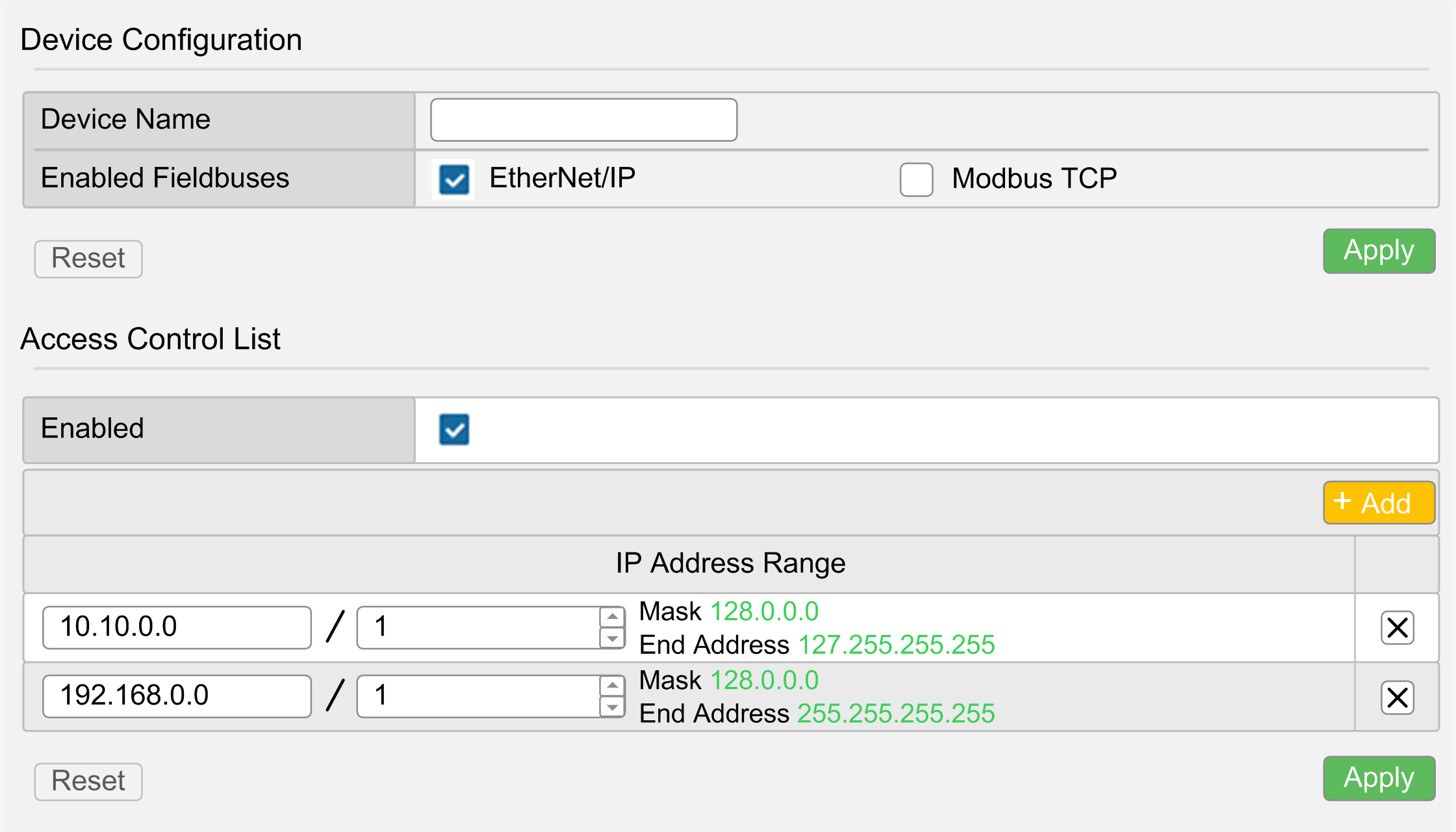
The following illustration shows the Setup sub-page:

The Setup sub-page allows you to change the configuration settings of the bus coupler:
|
Page |
Description |
|---|---|
|
Device Configuration |
|
|
Device Name |
Name of the bus coupler used in DCHP mode. If you modified the Device Name, do a power cycle of the bus coupler to take it into account. |
|
Enabled Fieldbuses |
Allows you to select the communication types: oEtherNet/IP oModbus TCP |
|
Reset |
Resets the configuration settings. |
|
Apply |
Saves the configuration settings. |
The Ethernet sub-page allows you to change the network settings:
|
Element |
Description |
|---|---|
|
Network Configuration |
|
|
Mode |
Allows you to select the following operating modes of the bus coupler: oManual oDHCP oBOOTP |
|
IP Address |
IP address of the bus coupler. For more information, refer to TM3 Bus Coupler - Hardware Guide. |
|
Subnet Mask |
Subnet mask of the bus coupler |
|
Gateway Address |
Gateway address of the bus coupler |
|
Apply(1) |
Saves the configuration settings. |
|
Reset |
Resets the configuration settings. |
|
Ping Test |
|
|
Target IP Address |
Allows you to enter the target IP address to check if the bus coupler can reach the device on the network. |
|
Ping |
Sends a message to the IP address. |
|
RSTP Configuration |
|
|
Enabled |
Enables or disables the RSTP configuration. |
|
Bridge Priority |
Configure the switch priority to be chosen as the root switch. A low number represents a high priority. |
|
Hello Time (seconds) |
Interval between the generation of spanning-tree configuration messages by the root switch. These messages mean that the switch is operational. |
|
Maximum Age (seconds) |
The number of seconds a switch waits without receiving spanning-tree configuration messages before attempting a configuration. |
|
Forward Delay (seconds) |
The number of seconds the port waits before changing from its spanning-tree learning and listening states to the forwarding state. |
|
Access Control List (ACL) |
|
|
Enabled |
Enables or disables the ACL management. Enable it to configure the IP address ranges allowed to communicate with the bus coupler. |
|
IP Address Range |
Shows the ranges of IP addresses. Each line corresponds to an IP address range allowed to communicate with the bus coupler. The first field represents the starting IP address. The second one is the number of free bits. The maximum number of ranges is 10. |
|
Reset |
Resets the configuration settings. |
|
Apply |
Saves the configuration settings. |
|
Add |
Adds a line of IP address range. |
|
(1) Modifying the Ethernet configuration requires to do a power cycle of the bus coupler to apply the configuration settings. |
|
The Firmware sub-page shows the firmware version of the TM3 bus coupler and allows you to update its firmware:
|
Element |
Description |
|---|---|
|
Current Firmware |
|
|
Firmware |
Firmware version |
|
Web interface |
Web server version |
|
Firmware Update Select a new firmware version |
|
|
Select |
Allows you to select the new firmware file of the bus coupler. |
|
Apply |
Allows you to apply the new firmware. |
NOTE: You cannot update the firmware when the TM3 bus coupler cyclically exchanges data with the logic/motion controller. To make sure the bus coupler is not exchanging data, see MONITORING.
|
Step |
Action |
|---|---|
|
1 |
Apply power to the bus coupler. |
|
2 |
Connect the Ethernet cable. |
|
3 |
Set the rotary switch ONES to AUTO. |
|
4 |
Log into the Web server. |
|
5 |
Click MAINTENANCE / Firmware. |
|
6 |
Click Select then select the firmware file. Result: A confirmation window is displayed. |
|
7 |
Click I agree. Result: At the end of the download and verification of the file, a confirmation window is displayed. |
|
8 |
Click Yes to close the confirmation window then click Apply. Result: At the end of the firmware update, a message is displayed to inform you whether the firmware update is completed successfully. |
MAINTENANCE / System Log Files
The System Log Files sub-page lists the log files to be used by Schneider Electric Technical Support:
|
Element |
Description |
|---|---|
|
Log Files |
|
|
Name |
Shows the list of the log files. |
|
Size |
Displays the size of the log files. |
|
Download |
Allows you to download the log files. |