The TM4ES4 Ethernet module provides:
oAn Ethernet interface to controller without an embedded Ethernet port.
oA second Ethernet port to controller with an embedded Ethernet port.
The module is also an Ethernet switch.
This table describes the main characteristics of the TM4ES4 Ethernet communication module:
|
Main Characteristics |
Value |
|---|---|
|
Standard |
|
|
Connector type |
4 RJ45 connectors for Ethernet communication |
|
Protocols |
Ethernet Modbus TCP Client/Server, Ethernet/IP Adapter, UDP, TCP, SNMP, OPC UA server and EcoStruxure Machine Expert. |
|
Grounding |
1 screw for functional ground connection |
|
Transfer rate |
100 Mbit/s maximum |
This table presents the TM4ES4 Ethernet features provided to controllers:
|
Controller |
Additional Ethernet Interface |
Ethernet Switch |
|---|---|---|
|
TM241C24• |
Yes, one Ethernet port to connect to either the control network or the device network |
Yes |
|
TM241C40• |
||
|
TM241CE24• |
Yes, one Ethernet port to connect to the control network. The Ethernet port embedded on the logic controller connects to the device network. |
Yes |
|
TM241CEC24• |
||
|
TM241CE40• |
||
|
TM251MESE |
No |
Yes |
|
TM251MESC |
The following figure shows an architecture example to connect a controller to an Ethernet network:

The following figure shows the main elements of the TM4ES4 module:

|
Label |
Elements |
Refer to … |
|---|---|---|
|
1 |
LED that displays the power supply status |
– |
|
2 |
4 Ethernet RJ45 connectors |
– |
|
3 |
Screw for functional ground connection |
|
|
4 |
Clip-on lock for 35 mm (1.38 in.) top hat section rail (DIN-rail) |
|
|
5 |
Connector for TM4 expansion modules (one on each side) |
– |
|
6 |
Locking device for attachment to the previous module |
– |
|
7 |
Clip for attachment to the previous module or the controller |
– |
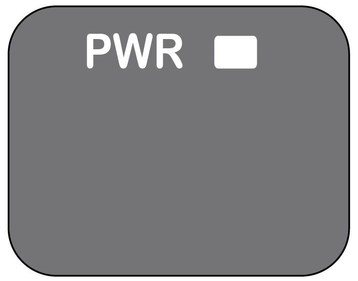
The figure shows the TM4ES4 status LEDs:

The table shows the description the TM4ES4 status LED:
|
LED |
Color |
Status |
Description |
|---|---|---|---|
|
PWR |
Green |
On |
Indicates that power is applied |
|
Off |
Indicates that power is removed |
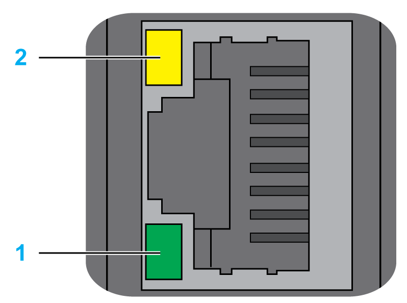
The figure shows the RJ45 connector status LEDs:

The table describes the RJ45 connector status LED:
|
Label |
Description |
LED |
||
|---|---|---|---|---|
|
Color |
Status |
Description |
||
|
1 |
Ethernet activity |
Green |
Off |
No activity |
|
On |
Transmitting or receiving data |
|||
|
2 |
Ethernet link |
Green/Yellow |
Off |
No link |
|
Solid yellow |
Link at 10 Mbit/s |
|||
|
Solid green |
Activity at 100 Mbit/s |
|||