Replacing the Motor and/or Gearbox (Optional Equipment)
The use and application of the information contained herein require expertise in the design and programming of automated control systems. Only you, the user, machine builder or integrator, can be aware of all the conditions and factors present during installation and setup, operation, repair, and maintenance of the machine or process.
You must also consider any applicable standards and/or regulations with respect to grounding of all equipment. Verify compliance with any safety information, different electrical requirements, and normative standards that apply to your machine or process in the use of this equipment.
The optional motor or gearbox of the is coupled by using a preloaded elastomer coupling.
NOTE: Before dismounting, note the mounting orientation of the motor and/or gearbox to remount the motor and/or gearbox in the same orientation.
|
|
|
HAZARD OF ELECTRIC SHOCK, EXPLOSION, OR ARC FLASH |
|
oDisconnect all power from all equipment including connected devices prior to removing any covers, or installing or removing any accessories, hardware, cables, or wires. oPlace a "Do Not Turn On" or equivalent hazard label on all power switches and lock them in the non-energized position. oWait 15 minutes to allow the residual energy of the DC bus capacitors to discharge. oMeasure the voltage on the DC bus with a properly rated voltage sensing device and verify that the voltage is less than 42.4 Vdc. oDo not assume that the DC bus is voltage-free when the DC bus LED is off. oDo not create a short-circuit across the DC bus terminals or the DC bus capacitors. oReplace and secure all covers, accessories, hardware, cables, and wires and confirm that a proper ground connection exists before applying power to the unit. |
|
Failure to follow these instructions will result in death or serious injury. |
|
|
|
UNINTENDED MOVEMENTS DUE TO DISMOUNTING |
|
Secure the moving parts of the axis mounted in a vertical or tilted position against unexpected movements. |
|
Failure to follow these instructions can result in death, serious injury, or equipment damage. |
You need the following tools to remove the motor and/or gearbox:
oSet of hex keys
NOTE: Do not use ball head hex keys. Excessive torque may cause the ball head to tear off. A torn off ball head is difficult to remove from the screw.
For suitable parts, refer to Replacement Equipment and Accessories.
Perform the following procedures to replace the motor and/or gearbox:
oPreparing the replacement of the motor and/or gearbox
oRemoving the motor from the gearbox
Preparing the Replacement of the Motor and/or Gearbox
|
Step |
Action |
|---|---|
|
1 |
If the axis is mounted tilted or vertically, remove the payload or support the payload and the end plates to keep it from falling. |
If possible, position the axis so that the back side of the motor points upwards during replacement.
NOTE: If the axis is mounted vertically or tilted, secure the end plates and the guide rods to keep them from falling.
|
Step |
Action |
|---|---|
|
1 |
Remove the cables of the motor. |
|
2 |
Secure the motor (4) to keep it from falling and remove the four screws (1) and the washers (2) by means of which the motor is mounted to the motor adapter plate (3). 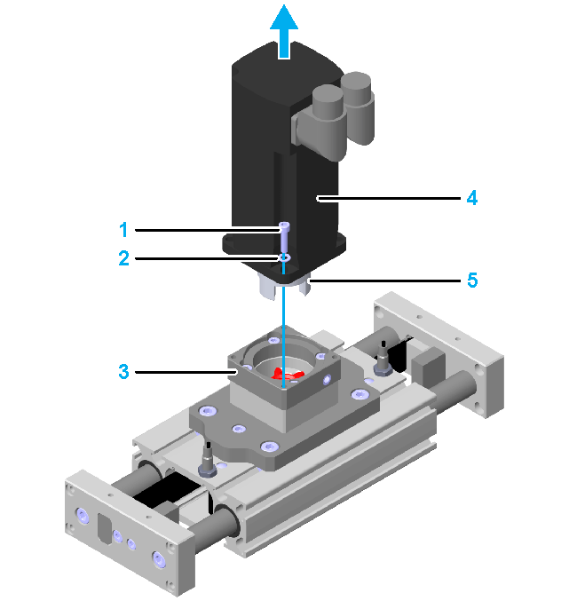
|
|
3 |
Pull the gearbox with the mounted flange plate and clamping hub (5) carefully upwards off the motor adapter plate. NOTE: This requires a greater force of up to 450 N (101.16 lbf). |
|
4 |
Loosen the clamping screw (6) on the clamping hub and remove the clamping hub carefully from the motor. 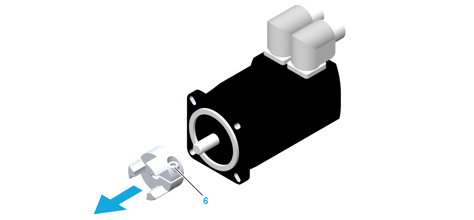
|
|
5 |
Mount the new motor as described in Mounting the Motor and/or Gearbox. NOTE: If the shaft dimensions of the new motor differ from the shaft dimensions of the previous motor, use a new appropriate clamping hub. For further information about appropriate clamping hubs, refer to Replacement Equipment and Accessories. |
If possible, position the axis so that the motor mounting side of the gearbox points upwards during replacement.
NOTE: If the axis is mounted vertically or tilted, secure the end plates and the guide rods to keep them from falling.
|
Step |
Action |
|---|---|
|
1 |
If a motor is mounted, remove the motor from the gearbox. For further information about removing the motor, refer to the corresponding gearbox manual. |
|
2 |
Secure the gearbox (4) to keep it from falling and remove the four screws (1) by means of which the flange plate (2) is mounted to the motor adapter plate (3). 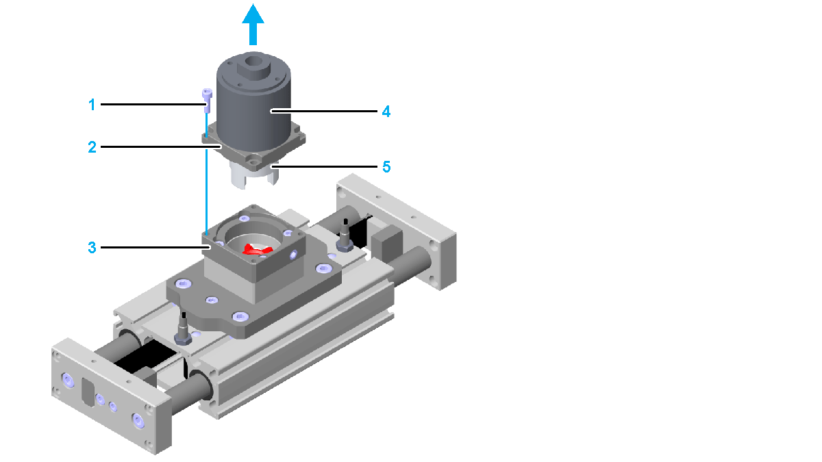
|
|
3 |
Pull the flange plate with mounted gearbox and clamping hub (5) carefully upwards off the motor adapter plate. NOTE: This requires a greater force of up to 450 N (101.16 lbf). |
|
4 |
Loosen the clamping screw (6) on the clamping hub and remove the clamping hub carefully from the gearbox. 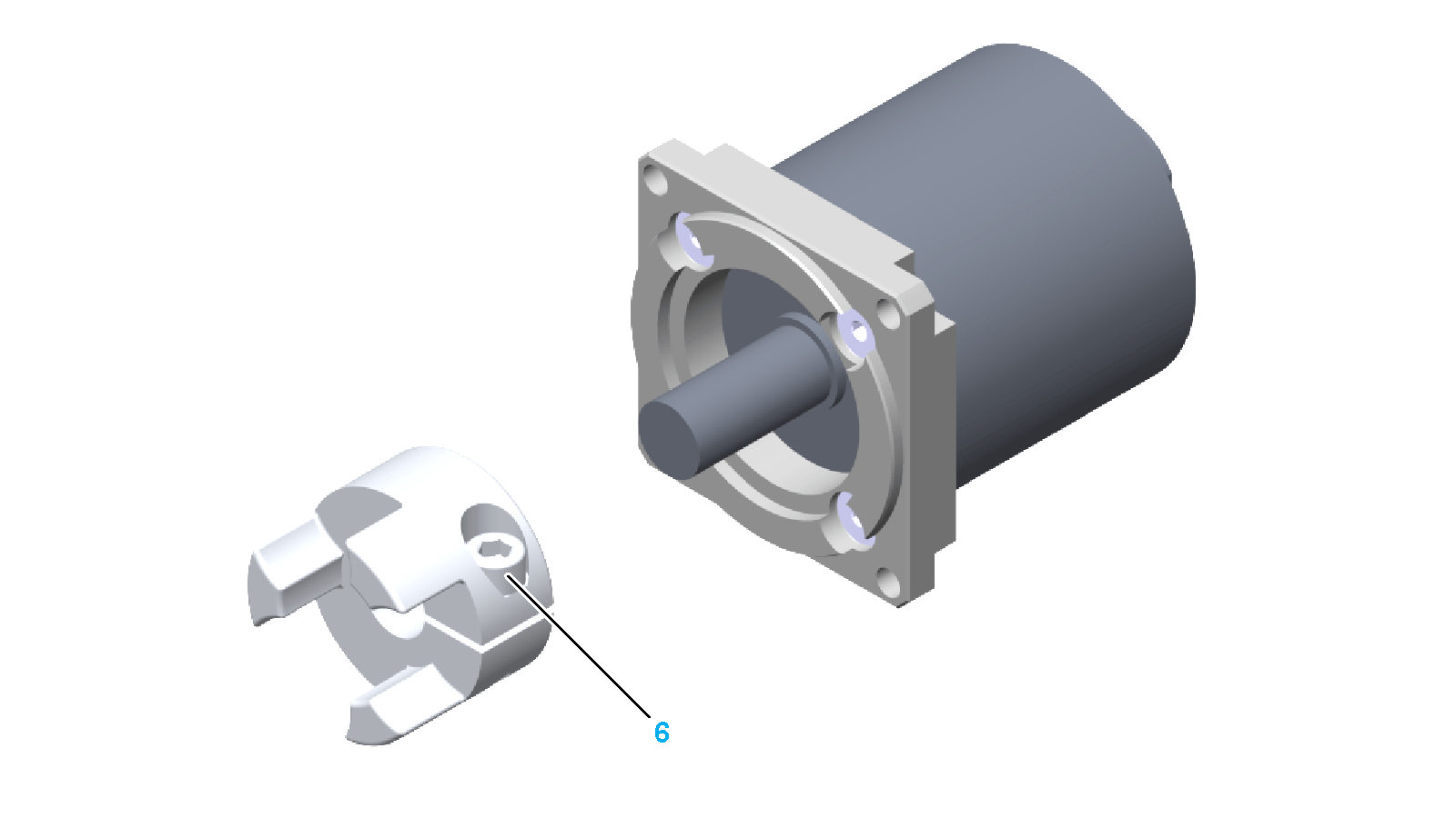
|
|
5 |
If the new gearbox does not have its own flange, remove the four screws (7) on the flange plate and then remove the flange plate. 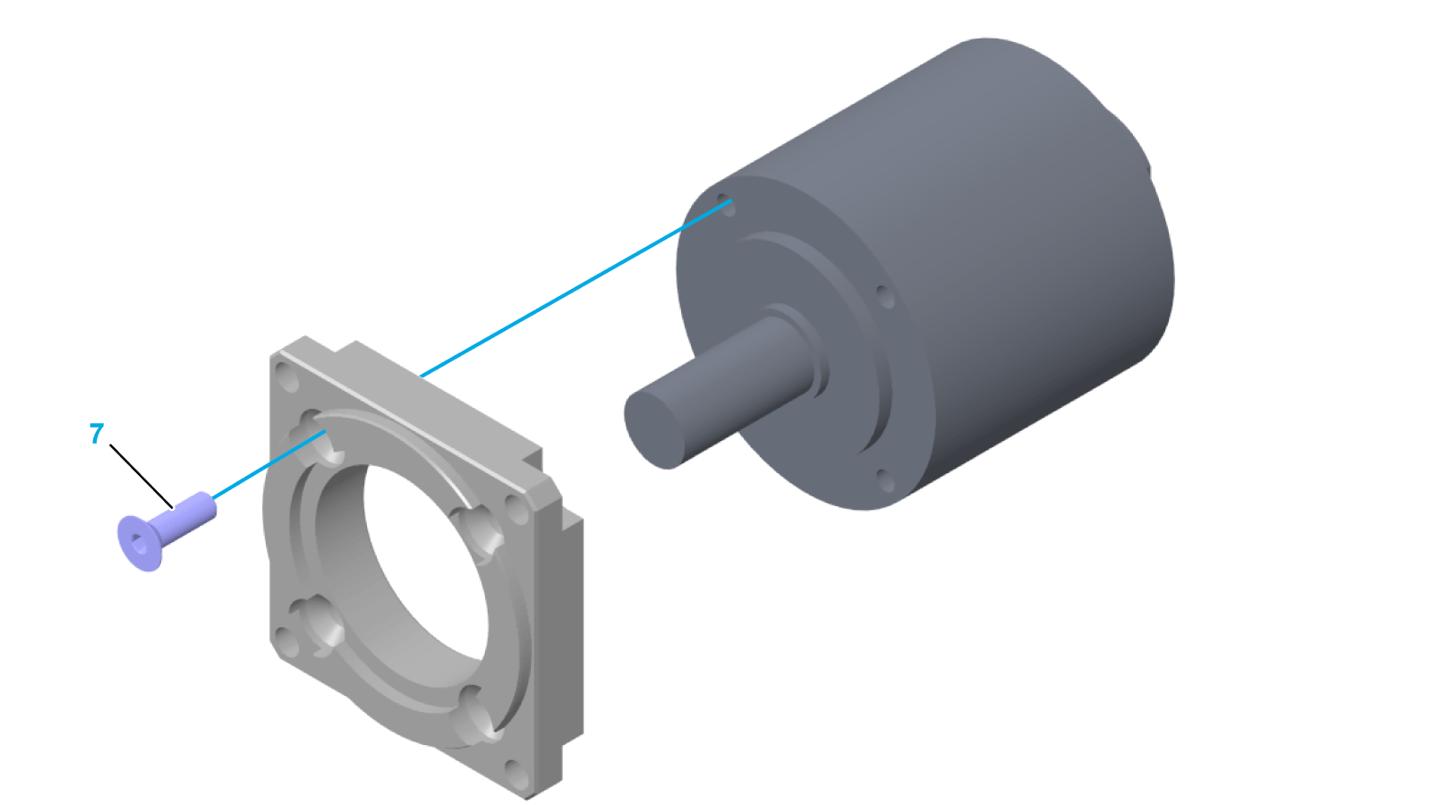
|
|
6 |
Mount the new gearbox as described in Mounting the Motor and/or Gearbox. NOTE: If the shaft dimensions of the new gearbox differ from the shaft dimensions of the previous gearbox, use a new appropriate clamping hub. For further information about appropriate clamping hubs, refer to Replacement Equipment and Accessories. |
Removing the Motor from the Gearbox
For information about removing the motor from the gearbox, refer to the corresponding gearbox manual.


