The following graphic shows a correct premounted lower arm:
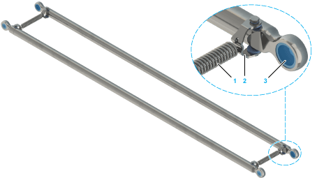
1 Springs
2 Spring brackets
3 Ball sockets
The lower arms can be damaged if they are mounted incorrectly and then pulled apart.
|
NOTICE |
|
INCORRECT MOUNTING OF LOWER ARMS |
|
Always hold the lower arms at the level of the lower arm heads to pull them apart. |
|
Failure to follow these instructions can result in equipment damage. |
Perform the following steps to mount the lower arms:
|
Step |
Action |
|---|---|
|
1 |
Verify that the lower arms show no visible signs of transport damage. If there are visible signs of transport damage, replace the lower arms. |
|
2 |
Pull the springs (1) across the spring brackets (2) located on the lower arms and connect each of the two lower arms to form a lower arm pair. 
|
|
3 |
Use the figure above to verify the correct alignment of the lower arm heads. |
|
4 |
Attach a total of two springs per lower arm pair, one at the lower end, one at the upper end. |
Verify that the spring windings are in contact with one another when they are completely contracted (no load condition). If the spring windings are not in contact, replace them.
|
NOTICE |
|
OVERSTRETCHING OF THE SPRINGS |
|
oNever pull the springs further apart than necessary to pull the lower arm over the second ball pin of the upper arm. oAvoid pulling the arms apart and simultaneously across both ball pins. oReplace springs after exceeding the elastic limit of the springs (overstretch). |
|
Failure to follow these instructions can result in equipment damage. |
|
Step |
Action |
|---|---|
|
1 |
Verify that the ball sockets (1) are located in each lower arm head. 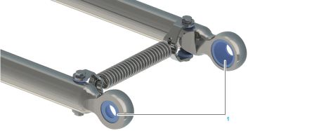
|
|
2 |
Verify that the springs (2) are embedded in the spring brackets (3). 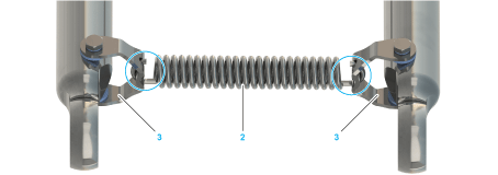
|
|
3 |
Pull a lower arm head (4) over a ball pin (5) of the upper arm. 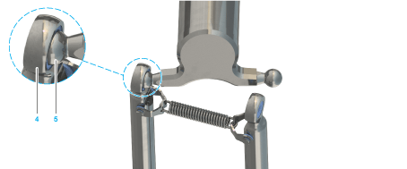
|
|
4 |
Pull the arm apart against the force of the spring in order to pull the lower arm (6) over the second ball pin (7) of the upper arm. 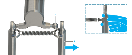
NOTE: Only touch the upper arm at its end and slightly rotate the aperture of the lower arm head in the direction of the ball pin. |
|
5 |
Position the aperture of the lower arm on the ball pin. 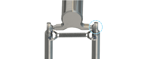
Result: The lower arm is hooked on the upper arm. |
|
6 |
Pull a lower arm head (8) over a ball pin (9) of the parallel plate. 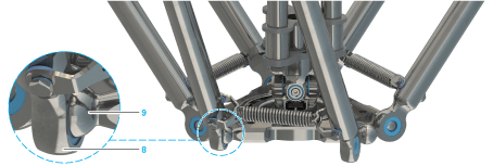
|
|
7 |
Pull the arm apart against the force of the spring in order to pull the lower arm (10) over the second ball pin (11) of the upper arm. 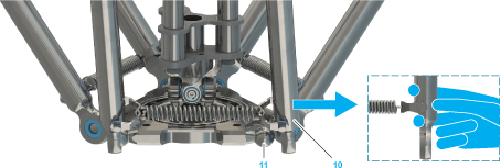
NOTE: Only touch the upper arm at its ends as shown in the small graphic and slightly rotate the aperture of the lower arm head in the direction of the ball pin. |
|
8 |
Position the aperture of the lower arm on the ball pin. 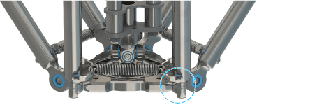
Result: The lower arm is hooked on the parallel plate. |
|
9 |
Repeat the process for all lower arms. |