Tools required:
o5 mm (0.197 in) hex key
o10 mm (0.39 in) socket
o7 mm (0.276 in) open wrench
oTorque wrench
oOil
Tools suggested:
oSyringe and tube
|
|
|
HAZARD OF ELECTRIC SHOCK, EXPLOSION, OR ARC FLASH |
|
oDisconnect all power from all equipment including connected devices prior to removing any covers or doors, or installing or removing any accessories, hardware, cables, or wires. oPlace a "Do Not Turn On" or equivalent hazard label on all power switches and lock them in the non-energized position. oWait 15 minutes to allow the residual energy of the DC bus capacitors to discharge. oMeasure the voltage on the DC bus with a properly rated voltage sensing device and verify that the voltage is less than 42.4 Vdc. oDo not assume that the DC bus is voltage-free when the DC bus LED is off. oBlock the motor shaft to prevent rotation prior to performing any type of work on the drive system. oDo not create a short-circuit across the DC bus terminals or the DC bus capacitors. oReplace and secure all covers, accessories, hardware, cables, and wires and confirm that a proper ground connection exists before applying power to the unit. oUse only the specified voltage when operating this equipment and any associated products. |
|
Failure to follow these instructions will result in death or serious injury. |
Initial position:
oRemove the ring holding the mechanical limit stops on axis 1 (if installed).
|
Step |
Action |
|---|---|
|
1 |
Loosen the breather (1). 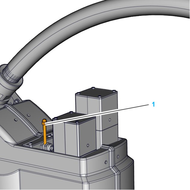
|
|
2 |
Remove the plug (2). 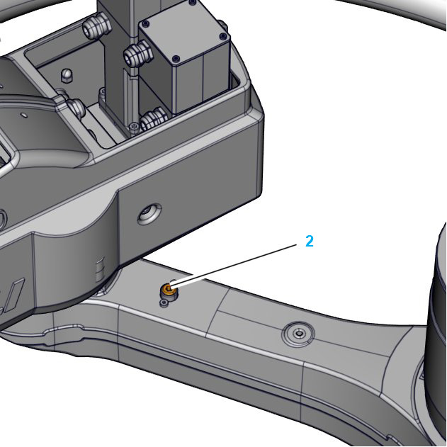
|
|
3 |
Partially unscrew the drain screw (3). 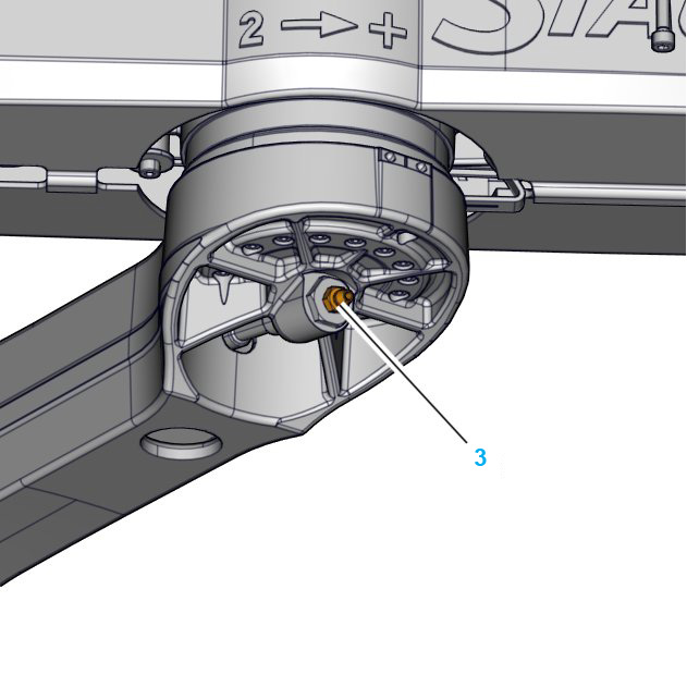
|
|
4 |
Suck out the used oil. |
|
5 |
Inject new oil until the oil level reaches the middle of the groove (4). 
|
|
6 |
Tighten the drain screw (3) to a torque level of 6 Nm (53 Nm).
|
|
7 |
Screw the plug (2) back in and tighten to a torque of 5 Nm (44 lbf-in).
|
|
8 |
Tighten the breather (1).
|
|
9 |
Verify the oil level of axis 2 again after a few rotations of the gearbox. For further information, refer to Verifying the Oil Level of Axis 2. |

