An incorrect installation of the cables may damage the insulation. Broken conductors in the cable or improperly connected connectors may promote arcing within the cable.
|
|
|
HAZARD OF ELECTRIC SHOCK, EXPLOSION, OR ARC FLASH |
|
oDisconnect all power from all equipment including connected devices prior to connecting any cables. oVerify the correct pin assignment of the connectors before connecting any cables. oVerify that the cable connectors are properly inserted and locked before applying power to the equipment. oDo not apply force to the cables. |
|
Failure to follow these instructions will result in death or serious injury. |
For further information about the assignment of the connectors, refer to Connection for 24 V Voltage.
|
NOTICE |
|
INCORRECT PAIRING OF MOTOR AND ENCODER CABLES |
|
Label the motor and associated encoder cables according to their pairing. |
|
Failure to follow these instructions can result in equipment damage. |
|
Step |
Action |
|---|---|
|
1 |
Feed the four power and encoder cables directly to the connections at the level of the base. Verify for a correct routing and fixing of the cables to prevent any collision of cables and moving parts. |
|
2 |
Connect the female connector of the motor supply cables to the connection plate connectors and tighten the union nut. NOTE: When tightening the union nut, ensure that the connection cables are not twisted. |
|
3 |
Connect the motor supply cables to the drive according to the wiring diagram of the Lexium 62 Cabinet Drive as described in the Lexium 62 Hardware Guide (refer to the connection details of the drive). |
|
4 |
Feed the cables for connection reference X1202 and reference X1210 directly to the connections at the level of the base. Verify for a correct routing and fixing of the cables to prevent any collision of cables and moving parts. |
|
5 |
Connect the cables to the connection reference X1202 and to the connection reference X1210 and tighten the union nut. |
|
6 |
Connect the 24 V cable of reference X1210 to the 24 V, 0 V, and the Lexium 62 Cabinet Drive at the control cabinet. For further information, refer to Connection for 24 V Voltage. |
|
7 |
Connect the connection cable of reference X1202 to the control cabinet according to the robot configuration: oFor standard configuration: connect the cable (part number VW3E4002R•••) to provide digital or analog input/output at the tool flange oFor configuration with ARMIO board: connect the cable (part number VW3E3067R•••) to the CAN bus connection at the Logic Motion Controller. For further information, refer to the Lexium 62 Hardware Guide. |
|
8 |
Connect the connectors to the connection cables at the tool flanges for the electrical connection according to the robot configuration: oSetting Up the Tool Interface Connection for the Standard Configuration or oSetting Up the Tool Interface Connection for the Configuration with ARMIO Board |
|
9 |
If necessary, connect user cables at the level of the arm 2. Fur further information: oFor STS40: refer to Connecting User Cables at STS40. oFor STS60/80: refer to Connecting User Cables at STS60/80. |
|
|
|
LOOSE WIRING OR CABLING CAUSES ELECTRIC SHOCK |
|
Verify wiring or cabling connections for correct connections. |
|
Failure to follow these instructions will result in death or serious injury. |
NOTE: When grounding the robot, use cables that comply with the applicable local standards, for example, cables that conform to NEC 70 / NFPA 79 in the USA.

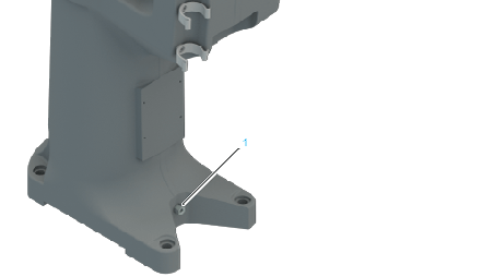
1 Ground connection at floor-mounted robot

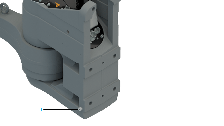
1 Ground connection at wall-mounted robot
|
|
|
ELECTRIC SHOCK DUE TO IMPROPER GROUNDING |
|
oGround robot components in accordance with local, regional and/or national standards and regulations at a single, central point. oVerify that the motors are connected to the central ground. |
|
Failure to follow these instructions will result in death or serious injury. |
Multipoint grounding is permissible if connections are made to an equipotential ground plane dimensioned to help avoid cable shield damage in the event of power system short-circuit currents.