The controller is the main element of the TM5 System.
The families of controllers are:
oModicon M258 Logic Controller
oModicon LMC058 Motion Controller
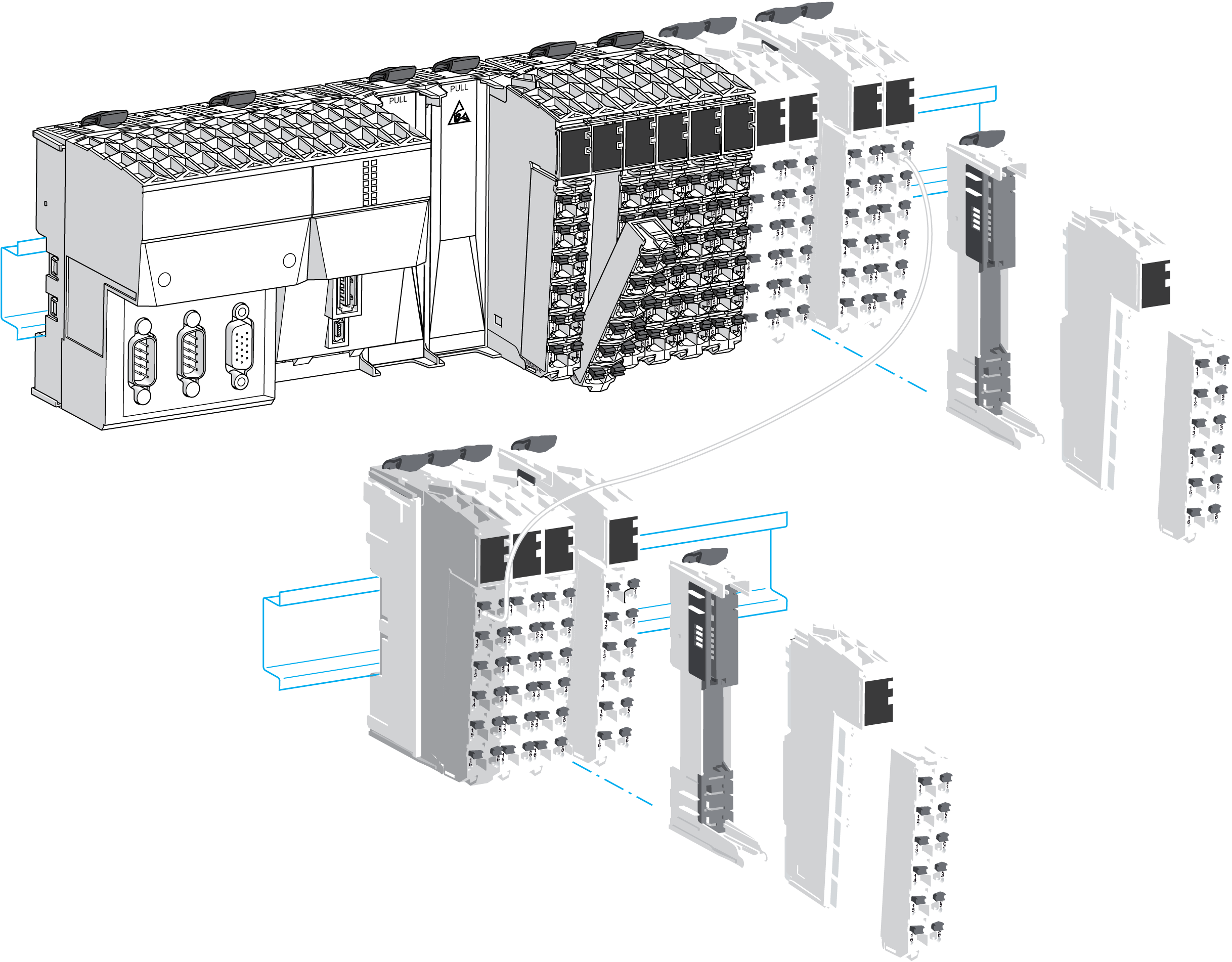
The following graphic depicts a typical TM5 System with the LMC058 motion controller:
Mechanical, hardware, and firmware features are described in the Modicon M258 Hardware Guide.
The following tables describes the controller references available for your TM5 System:
|
|
PCI |
CAN |
USB A |
USB Pgr |
Eth |
SL |
|---|---|---|---|---|---|---|
|
TM258LD42DT |
0 |
0 |
1 |
1 |
1 |
1 |
|
TM258LD42DT4L |
2 |
0 |
1 |
1 |
1 |
1 |
|
TM258LF42DT |
0 |
1 |
1 |
1 |
1 |
1 |
|
TM258LF42DT4L |
2 |
1 |
1 |
1 |
1 |
1 |
|
TM258LF66DT4L |
2 |
1 |
1 |
1 |
1 |
1 |
|
TM258LF42DR |
2 |
1 |
1 |
1 |
1 |
1 |
|
|
Embedded expert I/O |
Embedded regular I/O |
|||||||
|---|---|---|---|---|---|---|---|---|---|
|
|
Fast Inputs |
Fast Outputs |
Regular Inputs |
|
Digital Inputs |
Digital Outputs |
|
Analog Inputs |
|
|
TM258LD42DT |
2x |
5 |
2 |
2 |
1x |
12 |
12 |
0x |
0 |
|
TM258LD42DT4L |
2x |
5 |
2 |
2 |
1x |
12 |
12 |
1x |
4 |
|
TM258LF42DT |
2x |
5 |
2 |
2 |
1x |
12 |
12 |
0x |
0 |
|
TM258LF42DT4L |
2x |
5 |
2 |
2 |
1x |
12 |
12 |
1x |
4 |
|
TM258LF66DT4L |
2x |
5 |
2 |
2 |
2x |
12 |
12 |
1x |
4 |
|
TM258LF42DR |
2x |
5 |
2 |
2 |
2x |
6 |
6 Relays |
0x |
0 |
Modicon LMC058 Motion Controller
Mechanical, hardware, and firmware features are described in the Modicon LMC058 Hardware Guide.
The following tables describe the controller references available for your TM5 System:
|
|
PCI |
CAN |
USB A |
USB Pgr |
Eth |
SL |
ENC |
|---|---|---|---|---|---|---|---|
|
LMC058LF42 |
0 |
2 |
1 |
1 |
1 |
1 |
1 |
|
LMC058LF424 |
2 |
2 |
1 |
1 |
1 |
1 |
1 |
|
|
Embedded expert I/O |
Embedded regular I/O |
|||||||
|---|---|---|---|---|---|---|---|---|---|
|
|
Fast Inputs |
Fast Outputs |
Regular Inputs |
|
Digital Inputs |
Digital Outputs |
|
Analog Inputs |
|
|
LMC058LF42 |
2x |
5 |
2 |
2 |
1x |
12 |
12 |
0x |
0 |
|
LMC058LF424 |
2x |
5 |
2 |
2 |
1x |
12 |
12 |
1x |
4 |
M258 / LMC058 Controller Main Features
The following figure gives the main features of a controller:
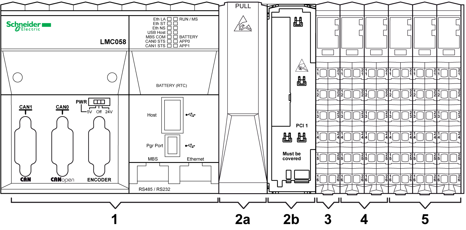
1 Controller
2a PCI slot with cover
2b PCI slot with cover removed
3 Controller Power Distribution Module (CPDM)
4 Embedded expert I/Os
5 Embedded regular I/Os
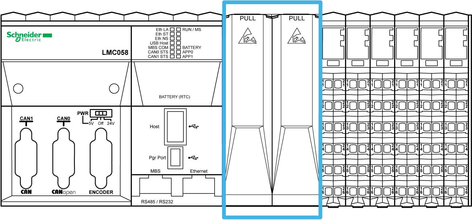
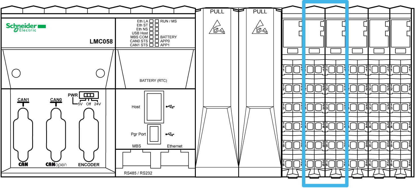
There are two PCI slots to connect up to two interface modules depending on the controller reference.
The following figure shows the location of PCI slots of the controllers:
The PCI modules are used for specific application expansions of the controller. They are inserted in the PCI slots of the controller:
|
Reference |
Type |
Description |
|---|---|---|
|
TM5PCRS2 |
Serial line |
TM5 interface electronic module, 1 RS-232, electrically isolated |
|
TM5PCRS4 |
Serial line |
TM5 interface electronic module, 1 RS-485, electrically isolated |
|
TM5PCDPS |
TM5 interface electronic module, 1 RS-485, electrically isolated |
For more details refer to the Modicon TM5 PCI Modules Hardware Guide.
|
NOTICE |
|
ELECTROSTATIC DISCHARGE |
|
oVerify that empty PCI slots have their covers in place before applying power to the controller. oNever touch an exposed PCI connector. |
|
Failure to follow these instructions can result in equipment damage. |
Controller Power Distribution Module (CPDM)
The distribution of power by the CDPM consists of three dedicated electrical circuits:
|
Designation |
Description |
|---|---|
|
24 Vdc embedded expert modules power |
24 Vdc power that serves the embedded expert I/O modules of the controller and the encoder (depends on references) |
|
24 Vdc Main power |
24 Vdc power that serves the electronics of the controller and generates independent power for: oPCI communication modules (depends on references), oModbus connected devices, oUSB keys, oElectronics of the embedded regular I/O, oTM5 power bus that serves the expansion modules. |
|
24 Vdc I/O power segment |
The 24 Vdc power that serves: othe embedded regular I/O, othe sensors and actuators connected to the embedded regular I/O, othe expansion modules, othe sensors and actuators connected to the expansion modules, othe external devices connected to the Common Distribution Modules (CDM). |
The following figure shows the terminal block assignments of the CPDM:
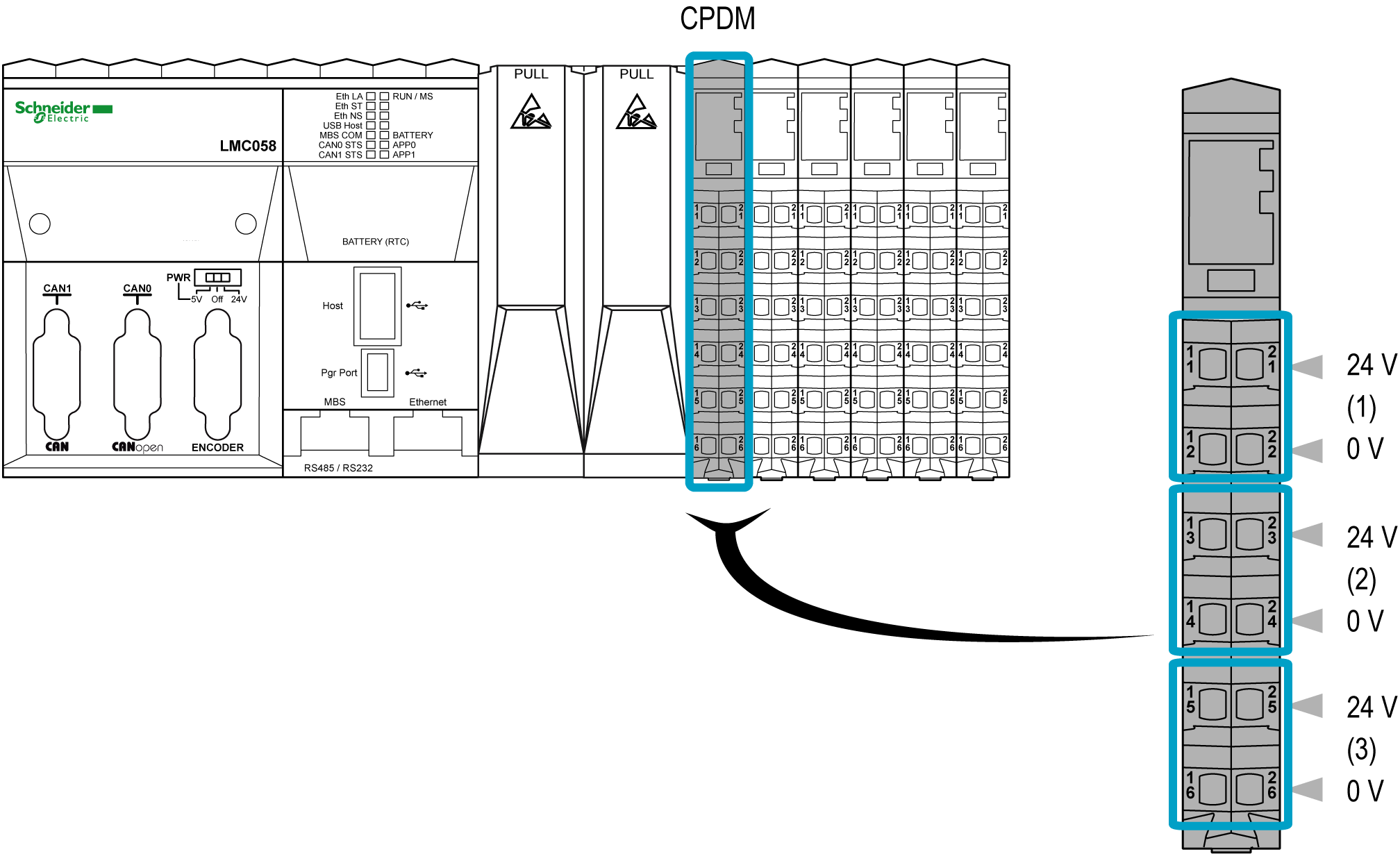
1 24 Vdc embedded expert modules power
2 24 Vdc Main power
3 24 Vdc I/O power segment
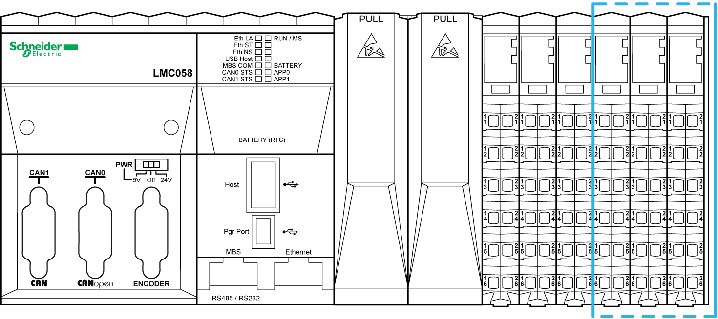
The following figure shows the location of the expert I/Os of the controller:
The controllers have two embedded expert I/O groups. Each group contains:
o5 fast inputs
o2 regular inputs
o2 fast outputs
Each group can be configured as:
o1 to 4 simple High Speed Counters (HSC)
o1 main HSC
o1 Pulse Width Modulated (PWM) output
o1 frequency generator
o1 encoder interface
Fast inputs resolution is up to 200 kHz.
NOTE: When a fast input is not used by special function, it can be used as a regular input.
Fast outputs resolution is up to 100 kHz.
NOTE: When a fast output is not used by special function, it can be used as a regular output.
The following figure shows the location of the embedded regular I/Os of the controller:
The following table gives a short description of the different regular I/Os embedded in the controller, depending on the controller reference: