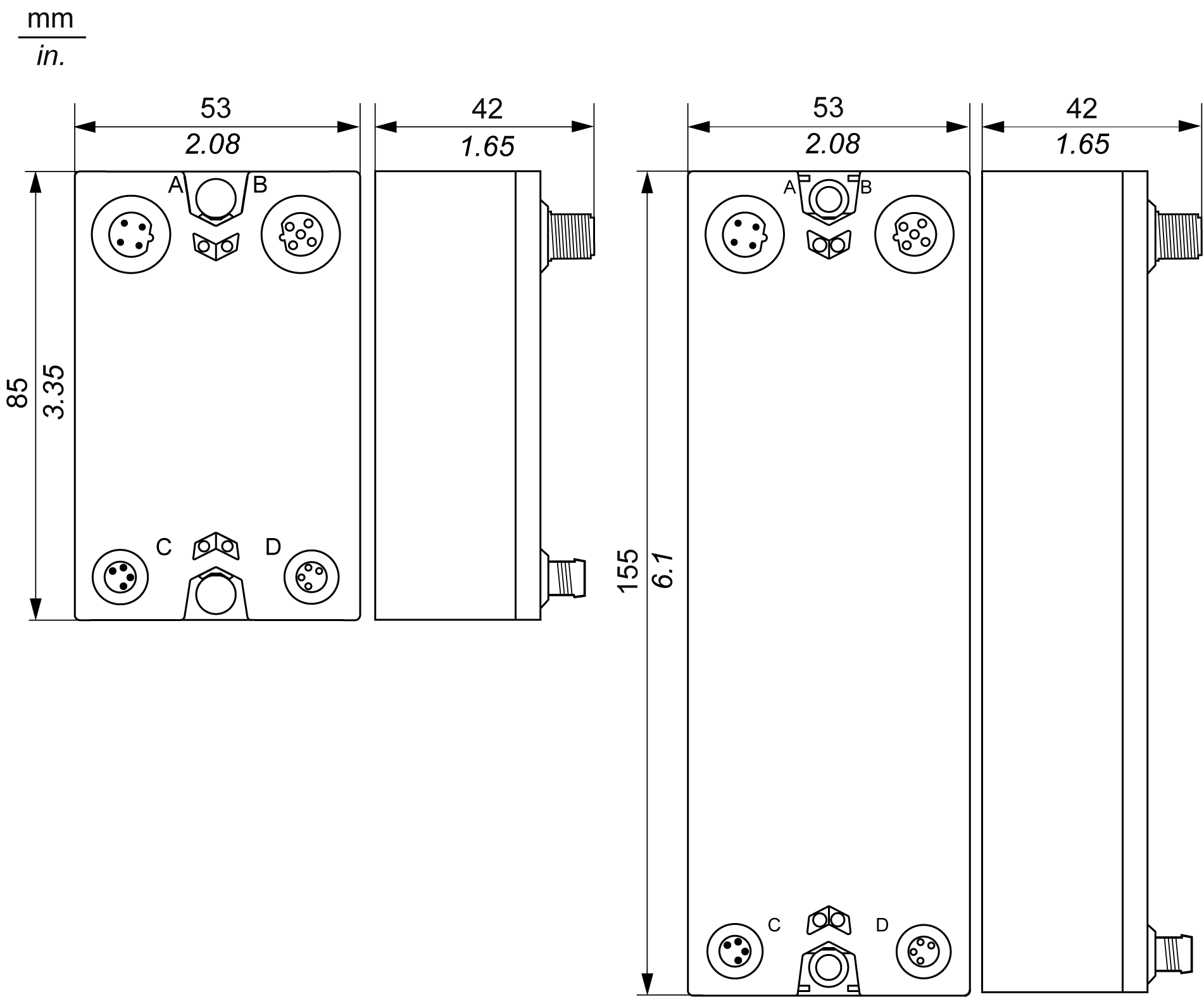
The following figure gives the dimensions of the size 1 (left) and size 2 (right) blocks:

The following tables give the sizes of the blocks:
|
TM7 field bus interface I/O blocks |
|||
|---|---|---|---|
|
Type of block |
Reference |
Size 1 |
Size 2 |
|
CANopen |
TM7NCOM08B |
x |
|
|
TM7NCOM16A |
|
x |
|
|
TM7NCOM16B |
|
x |
|
|
TM7 I/O Blocks |
|||
|---|---|---|---|
|
Type of block |
Reference |
Size 1 |
Size 2 |
|
Digital input |
TM7BDI8B |
x |
|
|
TM7BDI16B |
|
x |
|
|
TM7BDI16A |
|
x |
|
|
Digital mixed input/output |
TM7BDM8B |
x |
|
|
TM7BDM16A |
|
x |
|
|
TM7BDM16B |
|
x |
|
|
Digital output |
TM7BDO8TAB |
x |
|
|
Analog input |
TM7BAI4VLA |
x |
|
|
TM7BAI4CLA |
x |
|
|
|
TM7BAI4TLA |
x |
|
|
|
TM7BAI4PLA |
x |
|
|
|
Analog mixed input/output |
TM7BAM4VLA |
x |
|
|
TM7BAM4CLA |
x |
|
|
|
Analog output |
TM7BAO4VLA |
x |
|
|
TM7BAO4CLA |
x |
|
|
|
TM7 Power Distribution Block (PDB) |
|||
|---|---|---|---|
|
Type of block |
Reference |
Size 1 |
Size 2 |
|
PDB Power Distribution Block |
TM7SPS1A |
x |
|
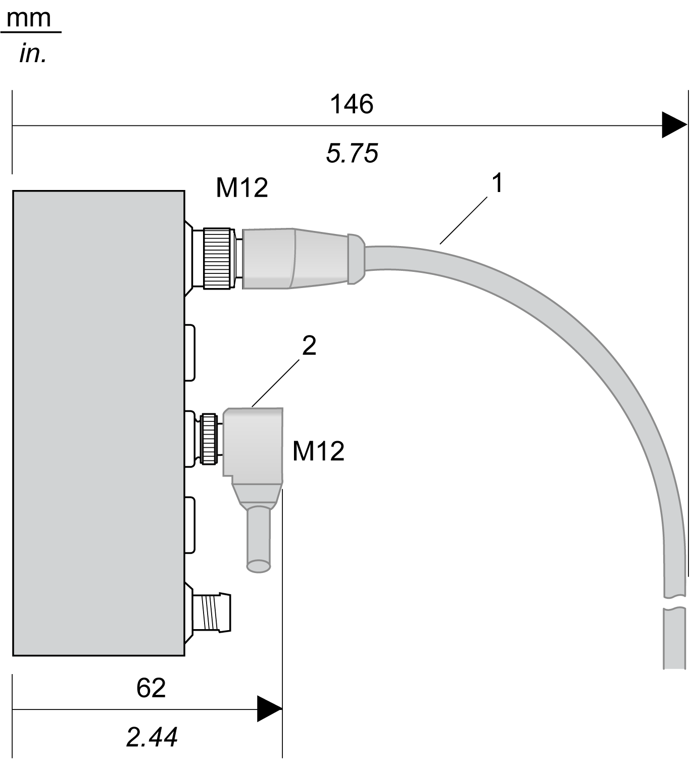
TM7 blocks can be installed side-by-side. However, you must observe the minimum spacings from the front face of each expansion block, based on cable connector type and cable bend radius.
The following figure shows an example of wire bending requirements for a block connected with pre-wired straight cables and elbowed cables:

1 Straight cable
2 Elbowed cable