In online mode, the Status tab of the bus coupler provides monitoring and diagnostics information for the bus coupler and connected modules.
Displaying Diagnostic Information
The bus coupler status register (object 1002) is accessible as a variable in EcoStruxure Machine Expert. Select the CANopen I/O Mapping tab to access the variable.
In addition, bus coupler and expansion module status information is also displayed under the Status tab of the bus coupler in EcoStruxure Machine Expert. For more information, refer to Status tabs description.
The bus coupler will send an EMCY telegram under certain internal error situations. The telegram is 8-bytes long and its structure is shown in table below.
|
EMCY Telegram Structure |
||||||||
|---|---|---|---|---|---|---|---|---|
|
Byte |
7 |
6 |
5 |
4 |
3 |
2 |
1 |
0 |
|
|
Manufacture status register |
Affected module number |
Error register |
EMCY error code |
||||
|
|
Object 1002H |
Object 1003H |
||||||
For example, in the following diagnostic message 'EMCY Code:7002; Register 80; Field:40 00 01 00 05.' (displayed in Status tab of the bus coupler in EcoStruxure Machine Expert).
o7002 matches the bytes 1 and 0 (EMCY error code)
o80 matches the byte 2 (EMCY Error register)
o40 00 01 00 matches the bytes 7, 6, 5 and 4 (Manufacture status register)
o05 matches the byte 3 (Affected module number)
For details of each portion of the telegram, refer to the Object Dictionary.
If an EMCY telegram is generated, the EMCY error code is displayed in the Web server. The full EMCY telegram can be seen in EcoStruxure Machine Expert, under TM3BC_CANopen > Status tab.
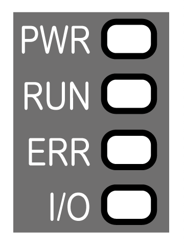
The following graphic shows the LEDs of TM3 CANopen bus coupler:

The following table describes the status LEDs:
|
LED |
Color |
Status |
Description |
|---|---|---|---|
|
PWR |
Green |
On |
Power is applied. |
|
Off |
Power is removed. All LED indicators are off. |
||
|
RUN |
Green |
On |
Device status is operational. |
|
Flickering |
In conjunction with a flickering ERR LED, automatic search for the bus communication speed. |
||
|
Flashing |
Device status is pre-operational. |
||
|
Single flash |
Device status is stopped. |
||
|
Triple flash |
Firmware upgrade. |
||
|
ERR |
Red |
On |
Bus off. |
|
Flickering |
In conjunction with a flickering RUN LED, automatic search for the bus communication speed. |
||
|
Flashing |
Invalid CANopen stack configuration. |
||
|
Single flash |
An internal error counter in the CAN controller has reached or exceeded the error frame limit threshold (error frame). |
||
|
Double flash |
Error control event detected. Detection of a guard event (NMT-Slave or NMT-master) or a heartbeat event (Heartbeat consumer). |
||
|
Triple flash |
Synchronization error detected: message not received from sync producer within the defined period. |
||
|
Quadruple flash |
Event Time error detected: An expected PDO has not been received before the Event Time elapsed. |
||
|
Off |
No error detected. |
||
|
I/O |
Green |
Flashing |
Device has received and applied the expansion modules configuration. |
|
On |
Device is communicating with the expansion modules. |
||
|
Red |
Single flash |
Expansion module configuration transfer timeout. |
|
|
Green Red |
Flashing On |
The physical configuration is inconsistent with the software configuration. No data exchange (status and I/O) is occurring. |
|
|
Green Red |
On On |
The physical configuration is inconsistent with the software configuration. I/O data is not applied. |
|
|
Green Red |
On Flashing |
At least one TM2 or TM3 expansion module did not respond to the bus coupler for 10 consecutive cycles. |
|
|
Off |
No configuration. Device is not communicating with the expansion modules. |
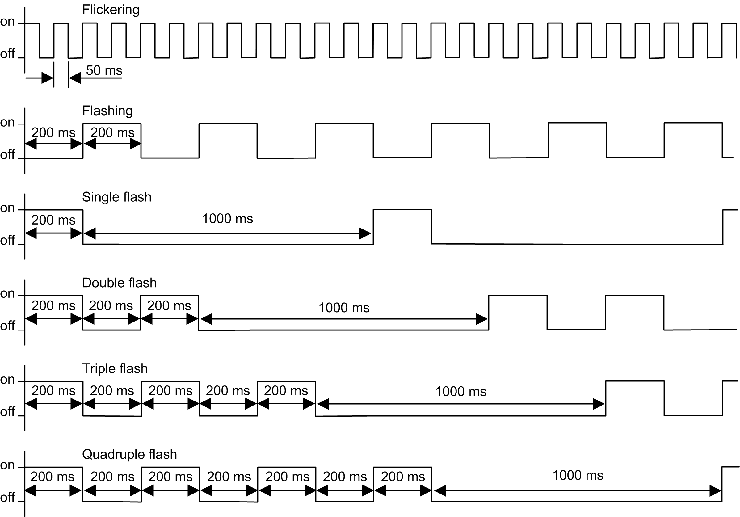
This timing diagram shows the different LED flashing behaviors:

NOTE: With the exception of the PWR LED, each LED is ON for a few seconds, then OFF during the boot sequence. The LED behavior rules apply when the boot is completed successfully.