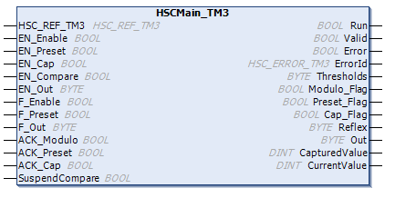
The Main type is always managed by an HSCMain_TM3 function block.
NOTE: At build time, an error is detected if the HSCMain_TM3 function block is used to manage a different HSC type.
Adding the HSCMain Function Block
|
Step |
Description |
|---|---|
|
1 |
Select the Libraries tab in the Software Catalog and click Libraries. Select Intern > IODrivers > TM3 HSC > HSC > HSCMain_TM3 in the list. |
|
2 |
Drag-and-drop the item onto the POU window. |
|
3 |
Edit the default Main type instance name to match the Instance name of the counter function block defined in the Configuration window. |

The tables below describe how the different pins of the function block are used in Modulo-loop mode.
This table describes the input variables:
|
Input |
Type |
Description |
|---|---|---|
|
HSC_REF_TM3 |
HSC_REF_TM3 |
Reference to the HSC instance. |
|
EN_Enable |
BOOL |
When EN input is configured: if TRUE, authorizes the counter enable via the Enable input. |
|
EN_Preset |
BOOL |
When SYNC input is configured: if TRUE, authorizes the counter to be initialized via the Preset input. |
|
EN_Cap |
BOOL |
When CAP input is configured: if TRUE, enables the Capture input. |
|
EN_Compare |
BOOL |
TRUE = enables the comparison function using Threshold 0, 1, 2, 3: obasic comparison (TH0, TH1, TH2, TH3 output bits) oreflex (Reflex0, Reflex1, Reflex2, Reflex3 output bits) oevents (to trigger external tasks on threshold crossing) |
|
EN_Out |
BYTE |
Set bits to 1 of corresponding physical outputs to echo the configured function value (Reflex or Stop) as a result of the comparison function. Only active when outputs configured in HSC editor: oBit 0: Output 0 enabled. oBit 1: Output 1 enabled. oBit 2: Output 2 enabled. oBit 3: Output 3 enabled. oBits 4...7: Not used. Association of HSC output Outx with physical output Qy is done by configuration. |
|
F_Enable |
BOOL |
TRUE = activates counter and takes into account pulses on the counter input. |
|
F_Preset |
BOOL |
On rising edge, resets, and initializes the counter. |
|
F_Out |
BYTE |
Set bits to 1 to force corresponding physical outputs to 1 if associated with HSC by configuration. Takes priority over EN_Out. Only active when outputs configured in HSC editor: oBit 0: Output 0 forced. oBit 1: Output 1 forced. oBit 2: Output 2 forced. oBit 3: Output 3 forced. oBits 4...7: Not used. Association of HSC output Outx with physical output Qy is done by configuration. |
|
ACK_Modulo |
BOOL |
On rising edge, resets Modulo_Flag. |
|
ACK_Preset |
BOOL |
On rising edge, resets Preset_Flag. |
|
ACK_Cap |
BOOL |
On rising edge, resets Cap_Flag. |
|
SuspendCompare |
BOOL |
TRUE = compare results are suspended: oThreshold, Reflex and Out bits maintain their last value. oEvents are masked. NOTE: EN_Compare, EN_Reflex, and F_Out remain operational while SuspendCompare is set. |
This table describes the output variables:
|
Output |
Type |
Comment |
|---|---|---|
|
Run |
BOOL |
TRUE = counter is activated. Only set to FALSE if the counter is disabled or an error is detected. |
|
Valid |
BOOL |
TRUE = indicates that output values on the function block are valid. |
|
Error |
BOOL |
TRUE = indicates that an error was detected. |
|
ErrorId |
HSC_ERROR_TM3 |
Indicates the value of the error detected. See HSC_ERROR_TM3 enumeration. |
|
Thresholds |
BYTE |
Bits set to 1 when CurrentValue ≥Threshold: oBit 0: CurrentValue ≥ Threshold 0 oBit 1: CurrentValue ≥ Threshold 1 oBit 2: CurrentValue ≥ Threshold 2 oBit 3: CurrentValue ≥ Threshold 3 oBits 4...7: Not used Only active when EN_Compare is set. |
|
Modulo_Flag |
BOOL |
Set to 1 when the counter roll overs the modulo or 0. |
|
Preset_Flag |
BOOL |
Set to 1 by the preset of the counter. |
|
Cap_Flag |
BOOL |
Set to 1 when a new capture value is stored in the Capture register. This flag must be reset before a new capture can occur. |
|
Reflex |
BYTE |
State of the reflex function: oBit 0: Reflex 0 oBit 1: Reflex 1 oBit 2: Reflex 2 oBit 3: Reflex 3 oBits 4...7: Not used |
|
Out |
BYTE |
State of the physical outputs: oBit 0: Output 0 oBit 1: Output 1 oBit 2: Output 2 oBit 3: Output 3 oBits 4...7: Not used Association of output Outx with physical output Qy is done by configuration. |
|
CapturedValue |
DINT |
Captured value, valid when Cap_Flag is TRUE. |
|
CurrentValue |
DINT |
The value of the counter. |