Communication Settings in Controller Selection Mode
Overview
The tab in controller selection mode is displayed when the mode has been selected for the parameter in the dialog box. The tab provides access to the Network Device Identification service that allows you to scan the Ethernet network for available controllers and to display them in a list. You can configure the parameters for the communication between the devices (referred to as controllers in this chapter) and the programming system.
The list of controllers contains those controllers in the network that have sent a response to the request of EcoStruxure Machine Expert. It may happen that the controller of your choice is not included in this list. This can have several causes. For causes and suitable solutions, refer to the chapter Accessing Controllers - Troubleshooting and FAQ.
tab in controller selection mode
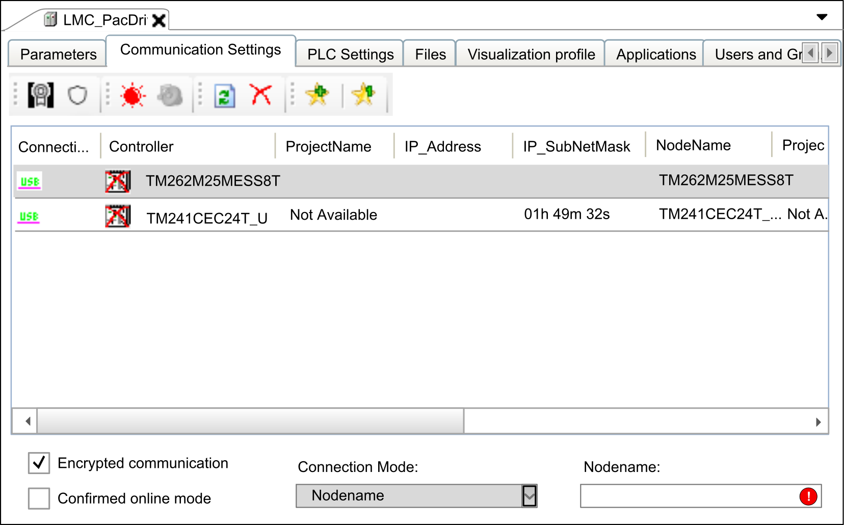
The tab provides the following elements:
-
Buttons in the toolbar
-
List providing information on the available controllers
-
Option, list, and box at the bottom of the tab
Description of the Buttons in the Toolbar
The following buttons are available in the toolbar:
|
Button |
Description |
|---|---|
|
|
Click this button to open the dialog box that allows you to select a new communication policy for the selected controller. |
|
|
Click this button to open the dialog box that allows you to modify the controller settings regarding the password policy that is being used. |
|
|
Click this button to cause the selected controller to indicate an optical signal: It flashes a control LED. This can help you to identify one controller if several controllers are used. The function stops on a second click or automatically after about 30 seconds.
NOTE: The optical signal is issued only by controllers that support this function.
|
|
|
Click this button to cause the selected controller to indicate an optical and an acoustical signal: It starts to beep and flashes a control LED. This can help you to identify one controller if several controllers are used. The function stops on a second click or automatically after about 30 seconds.
NOTE: The optical and acoustical signals are issued only by controllers that support this function.
|
|
|
Click this button to refresh the list of controllers. A request is sent to the controllers in the network. Controllers that respond to the request are listed with the updated values. Pre-existing entries of controllers are updated with every new request. Controllers that are already in the list but do not respond to a new request are not deleted. They are marked as inactive by a red cross being added to the controller icon. The button corresponds to the command that is provided in the contextual menu if you right-click a controller in the list. To refresh the information of a selected controller, the contextual menu provides the command . This command requests more detailed information from the selected controller.
NOTE: The command can also refresh the information of other controllers.
|
|
|
Controllers that do not respond to a network scan are marked as inactive in the list. This is indicated by a red cross being added to the controller icon. Click this button to remove the controllers that are marked as inactive controllers from the list.
NOTE: A controller can be marked as inactive even if this is not the case.
The contextual menu that opens if you right-click a controller in the list provides two other commands for removing controllers:
|
|
and |
You can use to adjust the selection of controllers to your personal requirements. This can help you keep track of many controllers in the network. A describes a collection of controllers that are recognized by a unique identifier. Click a favorite button (such as ) to select or deselect it. If you have not selected a favorite, all detected controllers are visible. You can also access via the contextual menu. It opens upon right-clicking a controller in the list. Move the cursor over a favorite button in the toolbar to view the associated controllers as a tooltip. |
List of Controllers
The list of controllers in the middle of the tab of the device editor lists those controllers that have sent a response to the network scan. It provides information on each controller in several columns. You can adapt the columns displayed in the list of controllers according to your individual requirements.
To achieve this, right-click the header of a column to open the dialog box.
You can create your own layout of this table. Click , and enter a name for your layout. Shift columns from the list of to the list of and vice versa by clicking the horizontal arrow buttons. To change the order of the columns in the list, click the arrow up and arrow down buttons.
Configuring Communication Settings
To set the parameters for communication between the programming system and a controller, proceed as follows:
|
Step |
Action |
|---|---|
|
1 |
Select the controller in the list of controllers. |
|
2 |
Right-click the controller entry and execute the command from the contextual menu. Result: The dialog box opens with the settings of the controller. 
NOTE: Most controllers provide a parameter (such as ) that helps prevent changing communication parameters of the controller.
|
|
3 |
Configure the communication parameters:
|
|
4 |
Click to transfer the settings to the controller. |
Carefully manage the IP addresses because each device on the network requires a unique address. Having multiple devices with the same IP address can cause unintended operation of your network and associated equipment.
| WARNING | |
|---|---|
Managing Favorites
To manage favorites in the list of controllers, proceed as follows:
|
Step |
Action |
|---|---|
|
1 |
Select the controller in the list of controllers. |
|
2 |
Right-click the controller and select one of the commands:
|
Option
When the option is selected under the tab, communication to the controller will be encrypted.
-
The controller must support TLS (Transport Layer Security).
-
A certificate must be available on the controller.
Consult the Programming Guide specific to your controller for information on the support of TLS.
The following scenarios are possible when you attempt to log into a controller using encrypted communication:
|
If... |
Then ... |
Comment |
|---|---|---|
|
If the controller does not support TLS (prerequisite 1 is not fulfilled) |
Then a message will be displayed when you attempt to log into the controller, indicating that the controller does not support TLS. |
The login is denied. |
|
If a certificate is not available on the controller (prerequisite 2 is not fulfilled) |
Then a message will be displayed when you attempt to log into the controller, indicating that encrypted communication could not be initialized successfully. |
The login is denied. |
|
If both prerequisites are fulfilled |
Then a message will be displayed when you attempt to log into the controller for the first time, requesting you to install the (untrusted) controller certificate to the local store of the PC running EcoStruxure Machine Expert. |
If you confirm with :
If you click :
|
For further information, refer to the document How To Manage Certificates on the Controller.
Option
The option causes EcoStruxure Machine Expert to display a message requiring confirmation when one of the following online commands is selected: . To disable the option and thereby delete the display of this message, clear this option.
Specifying Unique Device Names ()
The term is used as a synonym for the term device name. Since nodenames are also used to identify a controller after a network scan, manage them as carefully as IP addresses and verify that each nodename is unique in your network. Having multiple devices assigned the same nodename can cause unpredictable operation of your network and associated equipment.
| WARNING | |
|---|---|
Depending on the type of controller, the automatic creation of the (device name) may differ in procedure. To create a unique name, some controllers integrate their IP address, others use the MAC address of the Ethernet adapter. In this case, you do not have to change the name.
You can also assign a unique device name () as follows:
|
Step |
Action |
|---|---|
|
1 |
Right-click the controller in the list and execute the command from the contextual menu. Result: The dialog box opens. |
|
2 |
In the dialog box, enter a unique device name in the box . |
|
3 |
Click the button to confirm. Result: The device name you entered is assigned to the controller and is displayed in the column of the list.
NOTE: Device name and are synonymous.
|
Specifying the
The list at the lower left of the tab allows you to select a format for the connection address you have to enter in the field.
The following formats are supported:
-
Nodename via NAT (Remote TCP) (NAT = network address translation)
-
IP Address (PacDriveM only) (only available in service tools like Controller Assistant)
If you select the option from the list, you can enter the nodename, the IP address, or the connection URL (uniform resource locator) to specify the .
If you have selected another and you have specified an for this mode, the address you specified will still be available in the box if you switch to .
Example:
selected and address and nodename specified
If you switch to , the information is converted to a URL, starting with the prefix enodename3://
If an IP address has been entered for the connection mode, the information is converted to a URL starting with a prefix. For the , the prefix etcp3:// is used. For the , the prefix etcp4:// is used. For example, etcp4://<IpAddress>.
etcp2://. This is only available for PacDrive M controllers.
If a nodename has been entered for the connection mode (for example, when has been selected), the information is converted to a URL starting with the prefix enodename3://. For example, enodename3://<Nodename>.
If you select the option from the list, you can enter the nodename of a controller to specify the . The text box is filled automatically if you double-click a controller in the list of controllers.
Example: MyM238 (10.128.158.106)
If the controller you selected does not provide a nodename, the automatically changes to , and the IP address from the list is entered in the box.
If you select the option from the list, you can enter the IP address of a controller to specify the . The box is filled automatically if you double-click a controller in the list of controllers.
Example: 190.201.100.100
If the controller you selected does not provide an IP address, the automatically changes to , and the nodename from the list is entered in the box.
<Number>.<Number>.<Number>.<Number>
If you select the option from the list, you can connect to a controller using the TCP protocol. Enter the of the controller in the respective field. You can adapt the default setting for the if you are using network address translation (NAT).
Example: 190.201.100.100
<Number>.<Number>.<Number>.<Number>
If the controller is not listed in the list of controllers, click the button. If the controller sends a response to the network scan, an entry for this controller is added to the list of controllers. This entry is marked by the icon being displayed in the first column.
(PacDriveM only)
If you select the option from the list, you can enter the IP address of a controller to specify the . The box is filled automatically if you double-click a PacDrive M controller in the list of controllers.
Example: 190.201.100.100
<Number>.<Number>.<Number>.<Number>
If you select the option from the list, you can specify the address of a controller that resides behind a NAT router in the network. Enter the nodename of the controller, and the IP address or host name and port of the NAT router.
1 PC
2 NAT router
3 Target device
Example: 10.128.158.1061105 MyM238 (10.128.158.106)
<Number>.<Number>.<Number>.<Number>) or a valid host name for the .
Enter the port of the NAT router to be used. Otherwise, the default port is used.
The information you enter is interpreted as a URL that creates a remote TCP bridge - using TCP block driver - and then connects by scanning for a controller with the given nodename on the local gateway.
You can also scan a remote network via a remote controller (bridge controller). To achieve this, enter the , and click the refresh button right to the text field. The controllers that send a response to the remote network scan are listed in the list of controllers. Each of these entries is marked by the icon being displayed in the first column. To fill the list with more detailed information, right-click a controller entry and execute the command . If the controller supports this function, further information on the controller is added to the list. Consult the Programming Guide specific to your controller.
1 Refresh button
2 REM icon
In the following example, the , , and are scanned.
1 Local subnet
2 Remote subnet
3 Bridge controller
4 Controller 3
5 Controller 2
6 NAT router
7 PC
If you select the option (NAT = network address translation) from the list, you can specify the address of a controller that resides behind a NAT router in the network. Enter the IP address of the controller, and the IP address or host name and port of the NAT router.
1 PC
2 NAT router
3 Target device
Example: 10.128.154.2061105 192.168.1.55
<Number>.<Number>.<Number>.<Number>) or a valid host name for the .
Enter the port of the NAT router to be used. Otherwise, the default port is used.
Enter a valid IP address (format <Number>.<Number>.<Number>.<Number>) for the .
The information you enter is interpreted as a URL that creates a remote TCP bridge - using TCP block driver - and then connects by scanning for a controller with the given nodename on the local gateway. The IP address is searched in the nodename (such as MyController (10.128.154.207)).
You can also scan a remote network via a remote controller (bridge controller). To achieve this, enter the , and click the refresh button right to the text field. The controllers that send a response to the remote network scan are listed in the list of controllers. Each of these entries is marked by the icon being displayed in the first column. To fill the list with more detailed information, right-click a controller entry and execute the command . If the controller supports this function, further information on the controller is added to the list. Consult the Programming Guide specific to your controller.
1 Refresh button
2 REM icon
In the following example, the , , and are scanned.
1 Local subnet
2 Remote subnet
3 Bridge controller
4 Controller 3
5 Controller 2
6 NAT router
7 PC
If you select the option from the list, you can specify the address of a controller that resides behind or close to an EcoStruxure Machine Expert gateway router in the network. Enter the nodename of the controller, and the IP address or host name and port of the EcoStruxure Machine Expert gateway router.
1 PC / HMI
2 PC / HMI / devices with installed EcoStruxure Machine Expert gateway
3 Target device
Example: 10.128.156.281217 MyPLC
<Number>.<Number>.<Number>.<Number>) or a valid host name for the .
Enter the port of the gateway router to be used. Otherwise, the default EcoStruxure Machine Expert gateway port is used.
Do not use spaces at the beginning or end and do not use commas in the box.
The information you enter is interpreted as a URL. The gateway is scanned for a device with the given nodename that is directly connected to this gateway. Directly connected means in the EcoStruxure Machine Expert gateway topology it is the root node itself or a child node of the root node.
The graphic shows an example that allows a connection from the PC to the target controller 3 (item 4 in the graphic) by using the address of hop PC2 (item 5 in the graphic) that must have an EcoStruxure Machine Expert gateway installed.
1 Hop PC 1
2 Target controller 1: MyNotUniqueNodename
3 Target controller 2: MyNotUniqueNodename
4 Target controller 3: MyNotUniqueNodename
5 Hop PC 2
6 PC / HMI
7 Router
8 Ethernet
To verify whether the connection to a specific controller can be established, enter the , and click the button. If the controller sends a response to the network scan, an entry for this controller is added to the list of controllers. This entry is marked by the icon being displayed in the first column.
To scan a specific gateway for available controllers, enter the , and click the refresh button right to the text field. The controllers that send a response to the gateway scan are listed in the list of controllers. Each of these entries is marked by the icon being displayed in the first column. To fill the list with more detailed information, right-click a controller entry and execute the command . If the controller supports this function, further information on the controller is added to the list. Consult the Programming Guide specific to your controller.
1 Refresh button
2 GAT icon
The gateway that is scanned can be located on a PC or on an HMI that can reside in the local or in a remote subnet. In the following example, the bridge and are scanned.
1 Local subnet
2 Remote subnet
3 Target controller 1
4 Target controller 2
5 Gateway
6 PC
7 Ethernet
You can connect to the listed devices using the gateway.
If you select the option from the list, you can specify the address of a controller that resides behind or close to an EcoStruxure Machine Expert gateway router in the network. Enter the IP address of the controller, and the IP address or host name and port of the EcoStruxure Machine Expert gateway router.
1 PC / HMI
2 PC / HMI / devices with installed EcoStruxure Machine Expert gateway
3 Target device
Example: 10.128.156.281217 10.128.156.222
<Number>.<Number>.<Number>.<Number>) or a valid host name for the .
Enter the port of the gateway router to be used. Otherwise, the default EcoStruxure Machine Expert gateway port is used.
Enter a valid IP address (format <Number>.<Number>.<Number>.<Number>) for the .
The information you enter is interpreted as a URL. The gateway is scanned for a device with the given IP address. The IP address is searched in the nodename (such as MyController (10.128.154.207)).
The graphic shows an example that allows a connection from hop PC2 (item 5 in the graphic) that must have an EcoStruxure Machine Expert gateway installed to the target controller 3 (item 4 in the graphic).
1 Hop PC 1
2 Target controller 1: 10.128.156.20
3 Target controller 2: 10.128.156.20
4 Target controller 3: 10.128.156.20
5 Hop PC 2
6 PC
7 Router
8 Ethernet
To verify whether the connection to a specific controller can be established, enter the , and click the button. If the controller sends a response to the network scan, an entry for this controller is added to the list of controllers. This entry is marked by the icon being displayed in the first column.
To scan a specific gateway for available controllers, enter the , and click the refresh button right to the text field. The controllers that send a response to the gateway scan are listed in the list of controllers. Each of these entries is marked by the icon being displayed in the first column. To fill the list with more detailed information, right-click a controller entry and execute the command . If the controller supports this function, further information on the controller is added to the list. Consult the Programming Guide specific to your controller.
1 Refresh button
2 GAT icon
The gateway that is scanned can be located on a PC or on an HMI that can reside in the local or in a remote subnet. In the following example, the bridge and are scanned.
1 Local subnet
2 Remote subnet
3 Target controller 1
4 Target controller 2
5 Gateway
6 PC
7 Ethernet
You can connect to the listed devices using the gateway.
If you select the option from the list, you can specify a controller that resides behind a modem line.
1 PC
2 PC / MODEM
3 Target modem
4 Target device
5 Phone line
To establish a connection to the modem, click the button. In the dialog box, enter the of the target modem and configure the communication settings. Click to confirm and to establish a connection to the modem.
If the EcoStruxure Machine Expert gateway is stopped and restarted, any connection of the local gateway is terminated. EcoStruxure Machine Expert displays a message that has to be confirmed before the restart process is started.
After the connection to the modem has been established successfully, the button changes from to . The list of controllers is cleared and refreshed scanning the modem connection for connected controllers. You can double-click an item from the list of controllers or enter a nodename in the box to connect to a specific controller.
Click the button to terminate the modem connection and to stop and restart the EcoStruxure Machine Expert gateway. The list of controllers is cleared and refreshed scanning the Ethernet network.