Wiring Best Practices
Overview
This section describes the wiring guidelines and associated best practices to be respected when using the M241 Logic Controller system.
| DANGER | |
|---|---|
| WARNING | |
|---|---|
1 For additional information, refer to NEMA ICS 1.1 (latest edition), "Safety Guidelines for the Application, Installation, and Maintenance of Solid State Control" and to NEMA ICS 7.1 (latest edition), "Safety Standards for Construction and Guide for Selection, Installation and Operation of Adjustable-Speed Drive Systems" or their equivalent governing your particular location.
Wiring Guidelines
The following rules must be applied when wiring an M241 Logic Controller system:
-
I/O and communication wiring must be kept separate from the power wiring. Route these 2 types of wiring in separate cable ducting.
-
Verify that the operating conditions and environment are within the specification values.
-
Use proper wire sizes to meet voltage and current requirements.
-
Use copper conductors (required).
-
Use twisted pair, shielded cables for analog, and/or fast I/O.
-
Use twisted pair, shielded cables for networks, and fieldbus.
Use shielded, properly grounded cables for all analog and high-speed inputs or outputs and communication connections. If you do not use shielded cable for these connections, electromagnetic interference can cause signal degradation. Degraded signals can cause the controller or attached modules and equipment to perform in an unintended manner.
| WARNING | |
|---|---|
1Multipoint grounding is permissible (and in some cases inevitable) if connections are made to an equipotential ground plane dimensioned to help avoid cable shield damage in the event of power system short-circuit currents.
For more details, refer to Grounding Shielded Cables.
To conform to IEC 61010 standards, route primary wiring (wires connected to power mains) separately and apart from secondary wiring (extra low voltage wiring coming from intervening power sources). If that is not possible, double insulation is required such as conduit or cable gains.
Rules for Removable Screw Terminal Block
The following tables show the cable types and wire sizes for a 5.08 pitch removable screw terminal block (I/Os and power supply):

The use of copper conductors is required.
| DANGER | |
|---|---|
| DANGER | |
|---|---|
Removing the I/O Terminal Block
The following figure shows the removal of the I/O terminal block from the M241 Logic Controller:
|
Step |
Action |
|---|---|
|
1 |
Remove power from your controller. |
|
2 |
Pull down the protective cache: 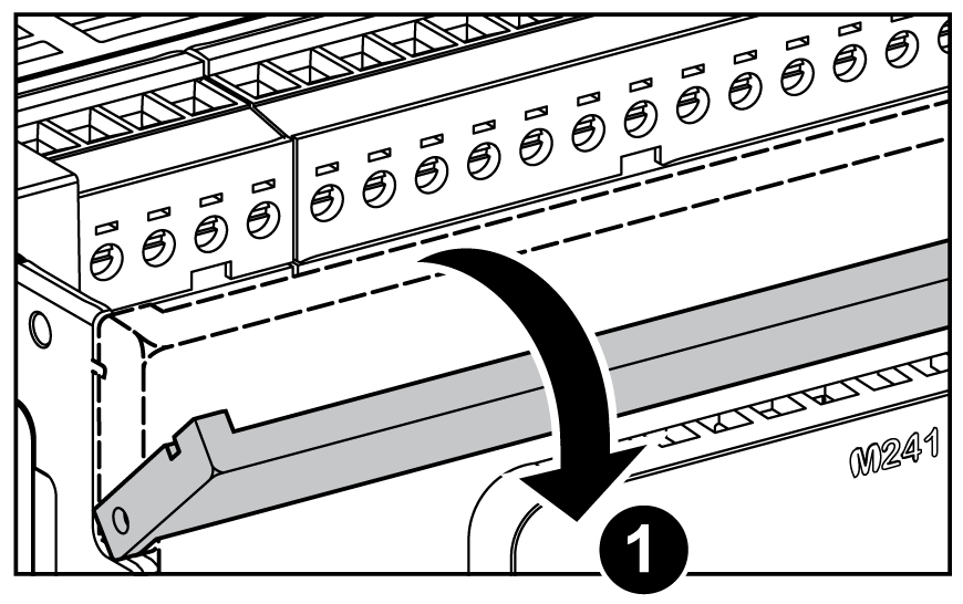
|
|
3 |
Press with a screwdriver through the terminal block front hole: 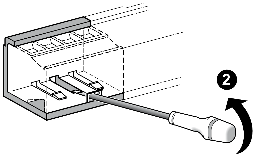
|
|
4 |
Remove the terminal block: 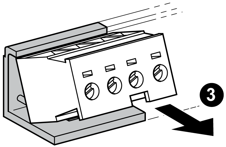
|
Protecting Outputs from Inductive Load Damage
Depending on the load, a protection circuit may be needed for the outputs on the controllers and certain modules. Inductive loads using DC voltages may create voltage reflections resulting in overshoot that will damage or shorten the life of output devices.
| CAUTION | |
|---|---|
If your controller or module contains relay outputs, these types of outputs can support up to 240 Vac. Inductive damage to these types of outputs can result in welded contacts and loss of control. Each inductive load must include a protection device such as a peak limiter, RC circuit or flyback diode. Capacitive loads are not supported by these relays.
| WARNING | |
|---|---|
AC-driven contactor coils are, under certain circumstances, inductive loads that generate pronounced high-frequency interference and electrical transients when the contactor coil is de-energized. This interference may cause the logic controller to detect an I/O bus error.
| WARNING | |
|---|---|
Protective circuit A: this protection circuit can be used for both AC and DC load power circuits.
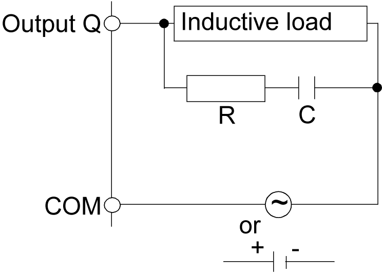
C Value from 0.1 to 1 μF
R Resistor of approximately the same resistance value as the load
Protective circuit B: this protection circuit can be used for DC load power circuits.
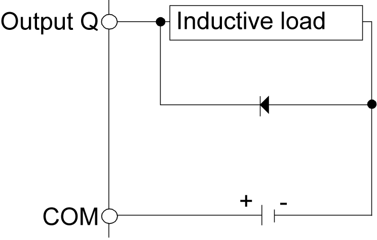
Use a diode with the following ratings:
-
Reverse withstand voltage: power voltage of the load circuit x 10.
-
Forward current: more than the load current.
Protective circuit C: this protection circuit can be used for both AC and DC load power circuits.
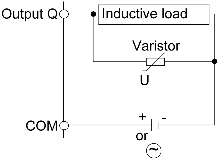
In applications where the inductive load is switched on and off frequently and/or rapidly, ensure that the continuous energy rating (J) of the varistor exceeds the peak load energy by 20 % or more.