DC Power Supply Characteristics and Wiring
DC Power Supply Voltage Range
If the specified voltage range is not maintained, outputs may not switch as expected. Use appropriate safety interlocks and voltage monitoring circuits.
| DANGER | |
|---|---|
| WARNING | |
|---|---|
DC Power Supply Requirements
The M241 Logic Controller and the associated I/O (TM2, TM3, and embedded I/O) require power supplies with a nominal voltage of 24 Vdc. The 24 Vdc power supplies must be rated Safety Extra Low Voltage (SELV) or Protective Extra Low Voltage (PELV) according to IEC 61140. These power supplies are isolated between the electrical input and output circuits of the power supply.
| WARNING | |
|---|---|
1 For compliance to UL (Underwriters Laboratories) requirements, the power supply must also conform to the various criteria of NEC Class 2, and be inherently current limited to a maximum power output availability of less than 100 VA (approximately 4 A at nominal voltage), or not inherently limited but with an additional protection device such as a circuit breaker or fuse meeting the requirements of clause 9.4 Limited-energy circuit of UL 61010-1. In all cases, the current limit should never exceed that of the electric characteristics and wiring diagrams for the equipment described in the present documentation. In all cases, the power supply must be grounded, and you must separate Class 2 circuits from other circuits. If the indicated rating of the electrical characteristics or wiring diagrams are greater than the specified current limit, multiple Class 2 power supplies may be used.
Controller DC Characteristics
The following table shows the DC power supply characteristics required for the controller:
|
Characteristic |
Value |
||
|---|---|---|---|
|
Rated voltage |
24 Vdc |
||
|
Power supply voltage range |
20.4...28.8 Vdc |
||
|
Power interruption time |
1 ms at 24 Vdc |
||
|
Maximum inrush current |
50 A |
||
|
Power consumption |
32.6 W |
max. 40.4 W(1) |
|
|
Isolation |
between DC power supply and internal logic |
Not isolated |
|
|
between DC power supply and protective earth ground (PE) |
500 Vac |
||
|
(1) Controller + 7 TM3 expansion modules |
|||
Power interruption
The TM241C••24T / TM241C•40T / TM241C••24U and TM241C•40U must be supplied by an external 24 V power supply equipment. During power interruptions, the M241 Logic Controller, associated to the suitable power supply, is able to continue normal operation for a minimum of 10 ms as specified by IEC standards.
The TM241C••24T / TM241C•40T / TM241C••24U and TM241C•40U must be supplied by an external 24 V power supply equipment. During power interruptions, the M241 Logic Controller, associated to the suitable power supply, is able to continue normal operation for a minimum of 10 ms as specified by IEC standards.
When planning the management of the power supplied to the controller, you must consider the power interruption duration due to the fast cycle time of the controller.
There could potentially be many scans of the logic and consequential updates to the I/O image table during the power interruption, while there is no external power supplied to the inputs, the outputs or both depending on the power system architecture and power interruption circumstances.
| WARNING | |
|---|---|
DC Power Supply Wiring Diagram
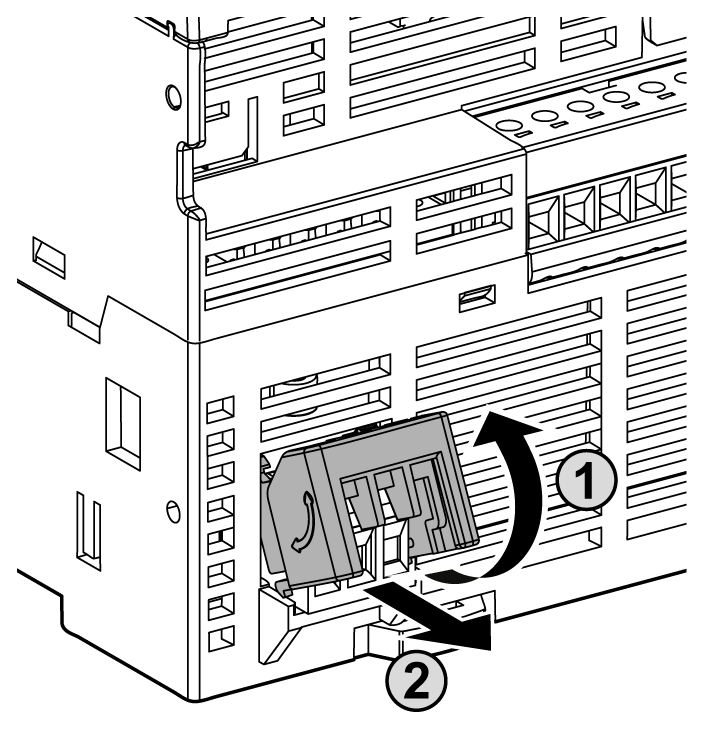
The following figure shows the power supply terminal block removal procedure:
The following figure shows the wiring of the DC power supply:
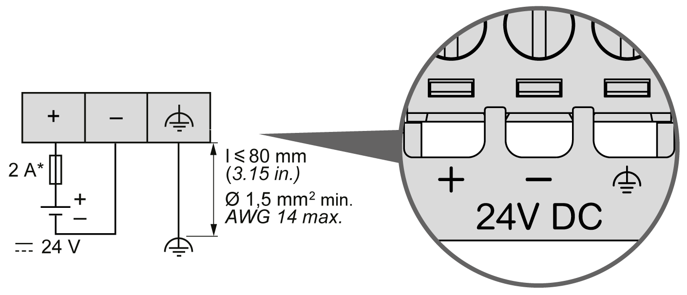
* Type T fuse
For more information, refer to the 5.08 pitch Rules for Removable Screw Terminal block.