IP Address Configuration
Introduction
There are different ways to assign the IP address to the added Ethernet interface of the controller:
-
Address assignment by DHCP server based on the Network Name of the Ethernet interface
-
Address assignment by BOOTP server based on the MAC address of the Ethernet interface
-
Fixed IP address
-
Post configuration file. If a post configuration file exists, this assignment method has priority over the others.
The IP address can also be changed dynamically through the:
-
Communication Settings tab in EcoStruxure Machine Expert
Carefully manage the IP addresses because each device on the network requires a unique address. Having multiple devices with the same IP address can cause unintended operation of your network and associated equipment.
| WARNING | |
|---|---|
Address Management
This diagram shows the different types of address systems for the controller:
The IP process restarts in the following cases:
-
Controller reboot
-
Ethernet cable reconnection
-
Application download (if IP parameters change)
-
DHCP or BOOTP server detected after a prior addressing attempt was unsuccessful.
Ethernet Configuration
In the , double-click or
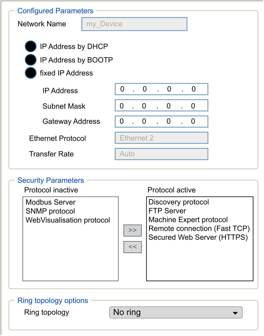
Note: If you are in online mode, you see the two windows. You cannot edit them. If you are in offline mode, you see the Configured Parameters window and, for Ethernet_2 the Ring topology options window. You can edit them.
This table describes the configured parameters:
|
Configured Parameters |
Description |
|
|---|---|---|
|
|
Name of the network link. Visible in online mode. |
|
|
|
Used as device name to retrieve IP address through DHCP, maximum 15 characters.
NOTE: The network name modification is applied at next power ON.
|
|
|
|
IP address is obtained by DHCP server. |
|
|
|
IP address is obtained by BOOTP server. MAC address is located on the front of the controller. |
|
|
|
IP address, Subnet Mask, and Gateway Address are defined by the user. |
|
|
|
Protocol type used: Ethernet 2 |
|
|
|
Speed and Duplex are in auto-negotiation mode. |
|
Default IP Address
The default IP addresses are:
-
10.10.x.y. for Ethernet_1
-
10.11.x.y. for Ethernet_2
When TM262• is not configured, TMSES4 boots and automatically gets its default IP address:
-
10.12.x.z for the first module
-
10.13.x.z for the second module
-
10.14.x.z for the third module
x represents the 5th and y or z represent the 6th bytes of interface MAC address. For example, with a MAC address of 00:80:F4:4E:02:5D, the IP address will be 10.12.2.93
The MAC address of the Ethernet port can be retrieved on the label placed on the front side of the controller. The MAC address of the TMSES4 port can be calculated with the controller MAC address port Ethernet_2.
The default subnet masks are:
-
255.255.0.0 for Ethernet_1
-
255.255.0.0 for Ethernet_2
Example of conversion:
|
Port |
MAC address |
IP address |
|---|---|---|
|
Ethernet_1 |
MAC@Eth1:00.80.F4.4E.24.10 |
10.10.36.16 |
|
Ethernet_2 |
MAC@Eth2:00.80.F4.4E.24.0B |
10.11.36.11 |
|
TMS_1 |
MAC@TMS:00.80.F4.50.24.0B |
10.12.36.11 |
|
TMS_2 |
MAC@TMS:00.80.F4.50.24.0C |
10.13.36.12 |
|
TMS_3 |
MAC@TMS:00.80.F4.50.24.0D |
10.14.36.13 |
Prohibited IP Addresses
USB Network address (192.168.200.0) and TMS Network address (192.168.2.0) are prohibited.
Subnet Mask
The subnet mask is used to address several physical networks with a single network address. The mask is used to separate the subnetwork and the device address in the host ID.
The subnet address is obtained by retaining the bits of the IP address that correspond to the positions of the mask containing 1, and replacing the others with 0.
Conversely, the subnet address of the host device is obtained by retaining the bits of the IP address that correspond to the positions of the mask containing 0, and replacing the others with 1.
Example of a subnet address:
|
IP address |
192 (11000000) |
1 (00000001) |
17 (00010001) |
11 (00001011) |
|
Subnet mask |
255 (11111111) |
255 (11111111) |
240 (11110000) |
0 (00000000) |
|
Subnet address |
192 (11000000) |
1 (00000001) |
16 (00010000) |
0 (00000000) |
Gateway Address
The gateway allows a message to be routed to a device that is not on the same network.
If there is no gateway, the gateway address is 0.0.0.0.
The default gateway address can be defined on any interface. You can only configure the default gateway on one interface. The traffic to unknown networks is sent through this interface. Please refer to IP Routing if you need to configure more than one interface.
Security Parameters
This table describes the different security parameters:
|
Security Parameters |
Description |
Default settings |
|---|---|---|
|
|
This parameter deactivates Discovery protocol. When deactivated, Discovery requests are ignored. |
Active |
|
|
This parameter deactivates the FTP server of the controller. When deactivated, FTP requests are ignored. |
Active |
|
|
This parameter deactivates the Machine Expert protocol on Ethernet interfaces. When deactivated, any Machine Expert request from any device is rejected. Therefore, no connection is possible on Ethernet from a PC with EcoStruxure Machine Expert, from an HMI target that wants to exchange variables with this controller, from an OPC server, or from Controller Assistant. |
Active |
|
|
This parameter deactivates the Modbus server of the controller. When deactivated, any Modbus request to the controller is ignored. |
Inactive |
|
|
This parameter deactivates the remote connection. When deactivated, Fast TCP requests are ignored. |
Active |
|
|
This parameter deactivates the secured Web server of the controller. When deactivated, HTTPS requests to the controller secured Web server are ignored. |
Active |
|
|
This parameter deactivates the SNMP server of the controller. When deactivated, SNMP requests are ignored. |
Inactive |
|
|
This parameter deactivates the WebVisualisation pages of the controller. When deactivated, HTTP requests to the controller WebVisualisation protocol are ignored. |
Inactive |
Ring Topology Options
This parameter is only available on the Ethernet_2 network.
This table describes the options:
|
Options |
Description |
|---|---|
|
|
If selected, verify that no ring is wired. |
|
|
First device of the ring topology. |
|
|
One of the devices in the ring topology. |
Each device in the ring topology must support the Rapid Spanning Tree Protocol (RSTP).
You can have up to 40 devices in the ring topology.