Calculating the Safety Response Time
General Information
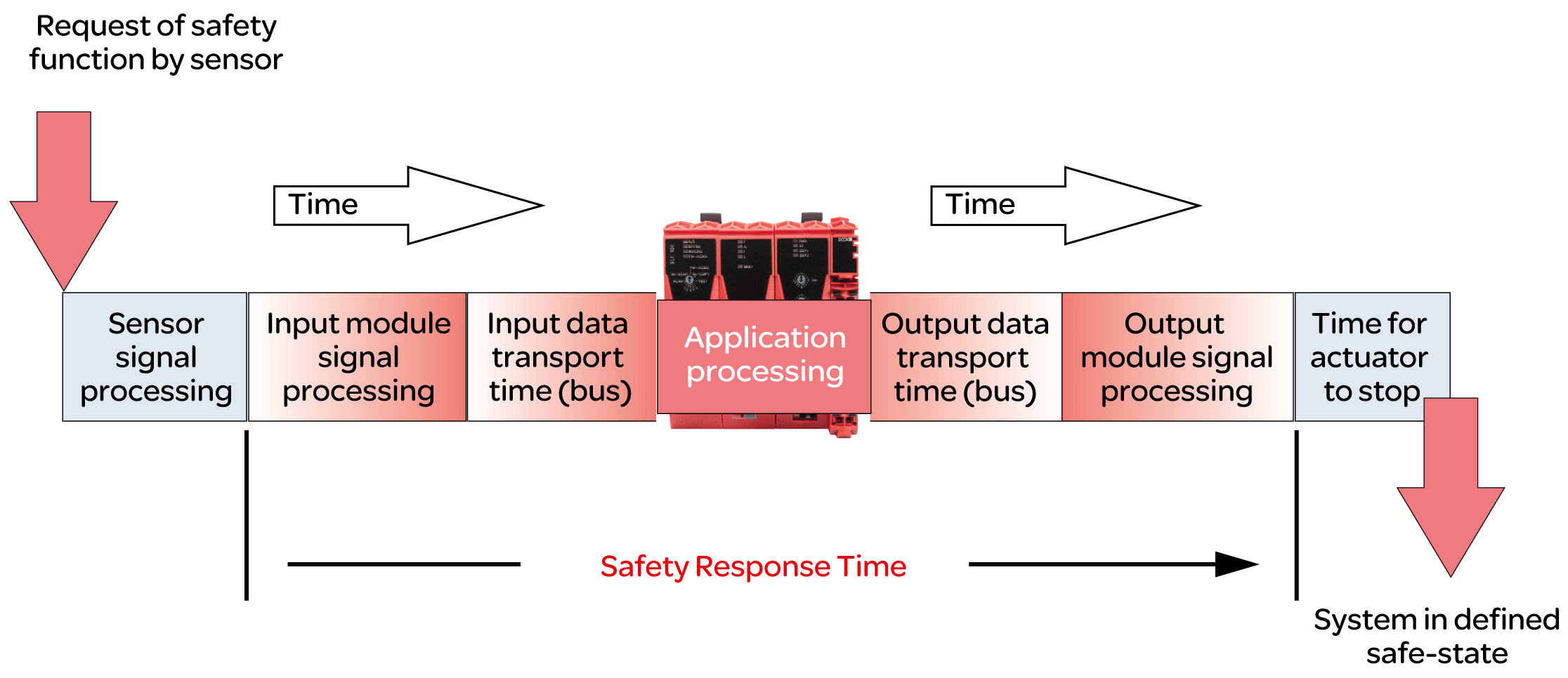
The safety response time is the time between the arrival of a signal from a sensor or input device (such as a light curtain or an emergency stop pushbutton) at the input channel of a safety-related TM5/TM7 input module and the deactivation signal at the output channel of a safety-related TM5/TM7 module as illustrated by the following figure:

To calculate the safety response time (SRT), the system adds up the following times:
-
Processing time in the safety-related input module (Processing Times in I/O Modules)
-
Input transport time (bus transfer from input module to SLC)
-
Output transport time (bus transfer from SLC to output module)
-
Processing time in the safety-related output module (Processing Times in I/O Modules)
As the figure illustrates, the SRT is not the same as the overall response time of a safety-related function as per ISO 13849-1, that is, the duration from the initial request of the safety-related function until the machine/process is in the defined state. The overall response time of a safety-related function as per ISO 13849-1 includes the response times of the equipment connected to the I/O modules, such as a light curtain to an input channel of an input module and a contactor connected to an output channel of an output module.
Typically, the defined safe state of a machine is a complete stop of machine functions identified to be hazardous. This means that you have to consider, among other things, the overall stopping performance as per, for example, ISO 13855, in your risk assessment and machine design. This overall stopping performance does not only include the maximum time between actuation of the safeguard (for example, emergency stop pushbutton engaged) and the output signal of output device reaching the deactivated state (for example, contactor de-energized). It also includes the stopping time which is the maximum time required to terminate hazardous machine functions after the output device has reached the deactivated state (for example, a motor has already reached a no-torque condition, but is still coasting down).
So, while the SRT is an essential part of the overall stopping performance and helps you to determine, for example, the minimum distance between a safety-related sensor (such as a light curtain) and the zone of operation, you need to consider additional factors not calculated by EcoStruxure Machine Expert - Safety in determining the response times required for your safety-related application.
| WARNING | |
|---|---|
| WARNING | |
|---|---|
For further information, refer to Safety Response Time of the EcoStruxure Machine Expert - Safety - User Guide.
Preconditions
Preconditions for calculating the safety response time:
-
Correct values are defined for the pertinent parameters of the Safety Logic Controller (refer to Configuring the Safety-Related Response Time Relevant Parameters for TM5CSLC100FS and TM5CSLC200FS and Configuring the Safety-Related Response Time Relevant Parameters for TM5CSLC100FS and TM5CSLC200FS).
-
Parameter ManualConfiguration is set to No for the I/O modules. With this setting, the values set for the Safety Logic Controller are also applied to the I/O modules.
-
If the ManualConfiguration parameter is set to Yes for the I/O modules: Make sure that correct values are defined for the relevant parameters of each module involved. Refer to the chapter Relevant Module Parameters for details.
Processing Times in I/O Modules
For safety-related Schneider Electric I/O modules, the following signal processing times must be considered.
Schneider Electric input modules:
-
Configured filter value of the switch-off filter
-
5000 µs when configuring the external clock signals
-
I/O update time for TM5SAI4AFS (analog current measurement) and TM5STI4ATCFS (analog temperature measurement)
-
Module processing time (timebase + I/O update time) for counter (TM5SDC1FS) module
Schneider Electric output modules:
-
TM5SDOxxxx modules: 800 µs max.
-
TM5SDM4DTRFS: 50 ms max. (integrated relay)
-
TM7SDM12DTFS: 1 ms max.
Calculating the Safety-Related Response Time
Procedure in Machine Expert - Safety:
|
Step |
Action |
|---|---|
|
1 |
|
|
2 |
You can now calculate the safety response time for individual input-output signal paths. To do so, select the input module for which the response time is to be calculated in the left list , and, if applicable, an input channel of this module in the center list . Result: The parameters set for the selected input module/channel are shown in the area below. As long as no module is selected, no parameters are shown. |
|
3 |
In the right list , select the output module for which the response time is to be calculated. Result: The dialog displays the calculated response times for the selected path. Document these values for verification purposes. |