Power and Encoder Connection
General
Hazardous voltages may be present at the motor connection. The motor itself generates voltage when the motor shaft is rotated. AC voltage can couple voltage to unused conductors in the motor cable.
| DANGER | |
|---|---|
| DANGER | |
|---|---|
The motor is designed for operation via a drive. Connecting the motor directly to AC voltage will damage the motor and can cause fires and initiate an explosion.
| DANGER | |
|---|---|
Drive systems may perform unintended movements if unapproved combinations of drive and motor are used. Even if motors are similar, different adjustment of the encoder system may be a source of hazards. Even if the connectors for motor connection and encoder connection match mechanically, this does not imply that the motor is approved for use.
| WARNING | |
|---|---|
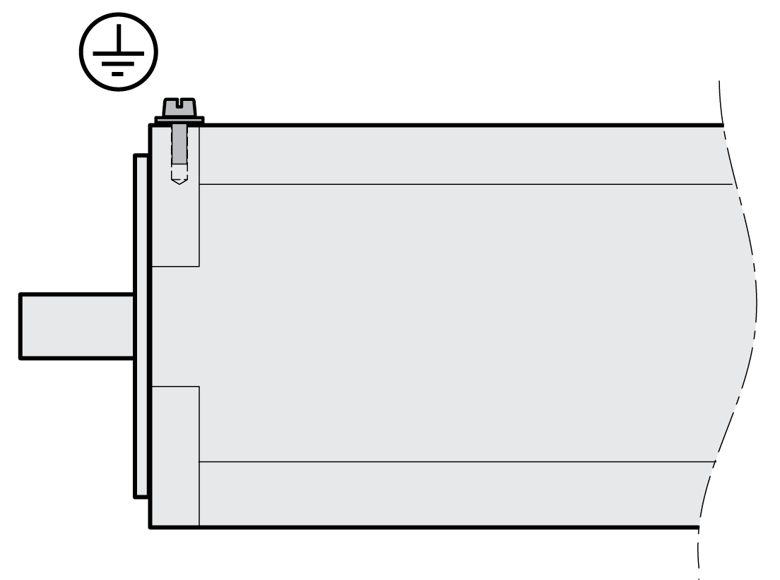
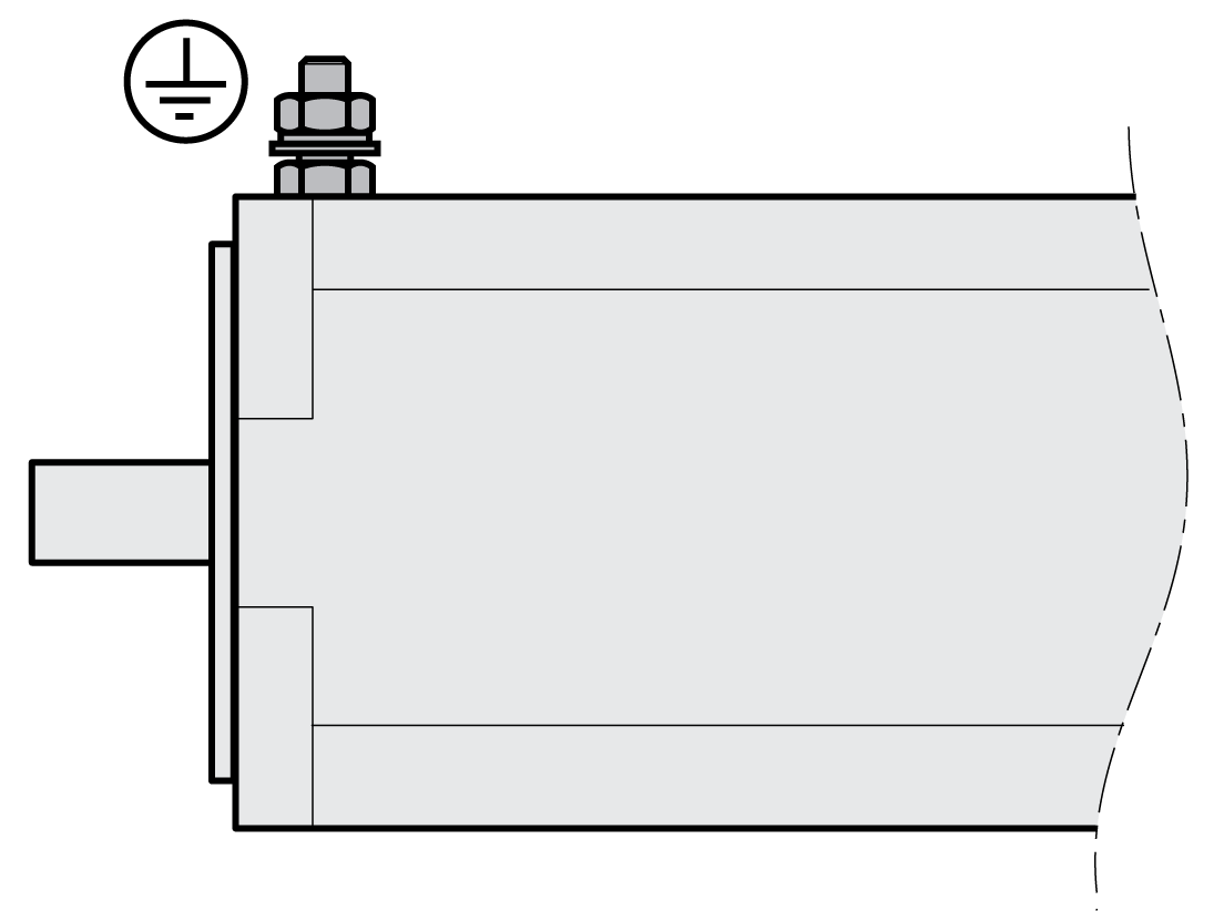
Protective Ground Conductor Connection
|
SH3040 |
SH3055 ... SH3205 |

|

|
Ground the motor via a grounding screw if grounding via the flange and the protective ground conductor of the motor cable is not sufficient. Use parts with suitable corrosion protection. Note the required tightening torque and the property class of the grounding screw, see Tightening Torque and Property Class Of Screws Used.
Assembling Cables
Insulate unused wires individually and, if necessary, at both ends of the wire.
-
Note the EMC requirements for motor cables and encoder cables, see Electromagnetic Compatibility (EMC).
-
Use equipotential bonding conductors for equipotential bonding.
Connecting the Cables
Incorrect installation of the cable may damage the insulation. Broken conductors in the cable or improperly connected connectors may promote arcing within the cable.
| DANGER | |
|---|---|
-
Connection:
-
For motors with two-cable connection:
Place the female connector of the motor cable onto the motor connector and tighten the union nut. Proceed in the same manner with the connection cable of the encoder system.
-
For motors with one-cable connection (SH3-OMC):
Place the female connector of the hybrid cable onto the motor connector and tighten the union nut.
-
-
Keep the cables from being twisted when tightening the union nut.
-
Connect the cables to the servo drive according to the wiring diagram of the servo drive.
-
Ground the shield to a large surface area. See the user guide of the servo drive for information on connecting the shield.