Rotary Switch
Overview
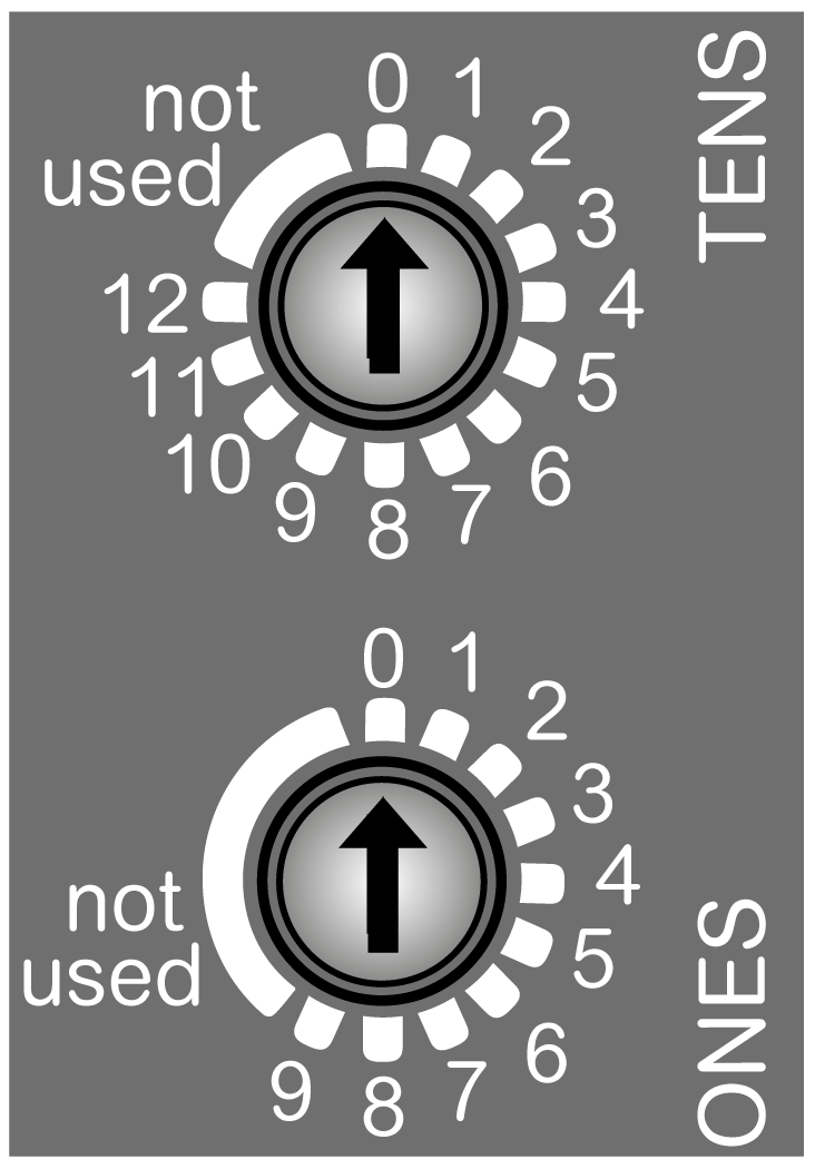
The two rotary switches located on the front panel of the TM3 CANopen bus coupler are used to set the CANopen bit rate and CANopen NodeID.
Default values on the rotary switches are:
-
0 for TENS
-
0 for ONES

(TENS) Set the bit rate/represents the tens numbered 0 to 120.
(ONES) Authorize to set the bit rate when set to not used position/represents the numbers 0 to 9.
Setting the Bit Rate
The TM3 CANopen bus coupler detects a new bit rate selection by the rotary switches only during power up. The bit rate is written to non-volatile memory.
Set the ONES rotary switch to any of the unnumbered positions (not used) to set a particular bit rate with the TENS rotary switch.
Bit rate can also be set and verified via the web server. For more information, refer to the Modicon TM3 Bus Coupler Programming Guide.
To set the bit rate, follow the steps below:
|
Step |
Action |
Comment |
|---|---|---|
|
1 |
Remove power to the bus coupler. |
The bus coupler detects the changes only at the next power up cycle. |
|
2 |
With a 2 mm or 2.5 mm slotted (flathead) screwdriver, set the ONES rotary switch to any of the unnumbered positions (not used).
NOTE: Rotary switch is designed to be torqued normally by hand. Axial force must be inferior to 2 N.
|
Setting the rotary switch to any of these unnumbered positions prepares the bus coupler to accept a new bit rate. |
|
3 |
With a 2 mm or 2.5 mm slotted (flathead) screwdriver, set the TENS rotary switch to the position that corresponds to your selected bit rate. |
Use the bit rate selection table below to determine the position of the rotary switch. |
|
4 |
Apply power to the bus coupler. |
The bus coupler reads the rotary switch settings only during power up. |
|
5 |
Wait for the RUN and the ERR LEDs to flash 3 times, then remain solid. |
The bus coupler has written the new bit rate setting to memory. |
|
6 |
Remove power to the bus coupler and set the CANopen address using the rotary switches, as described below in Setting the CANopen address. |
The bit rate has been established for the bus coupler. It must be followed by the address setting to operate. |
Bit-rate Selection Table
The following table shows the rotary switch positions and the bit rate:
|
Position TENS rotary switch |
Bit rate |
|---|---|
|
0 |
Not used |
|
1 |
20 kbits/s |
|
2 |
50 kbits/s |
|
3 |
125 kbits/s |
|
4 |
250 kbits/s |
|
5 |
500 kbits/s |
|
6 |
800 kbits/s |
|
7 |
1 Mbits/s |
|
8 |
Automatic bit-rate detection |
|
9 |
250 kbits/s (default value) |
|
10...12 |
Not used |
CANopen Bit Rate Setting Example
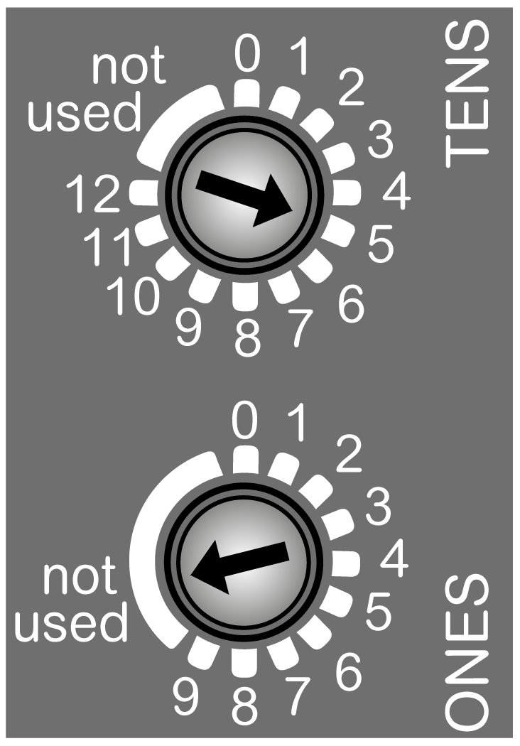
The following figure shows an example when the bit rate is configured to 500 kbits/s:

(TENS) Set to 5 to configure the bit rate to 500 kbits/s.
(ONES) Set to the not used position to authorize the bit rate setting.
Setting the CANopen Address
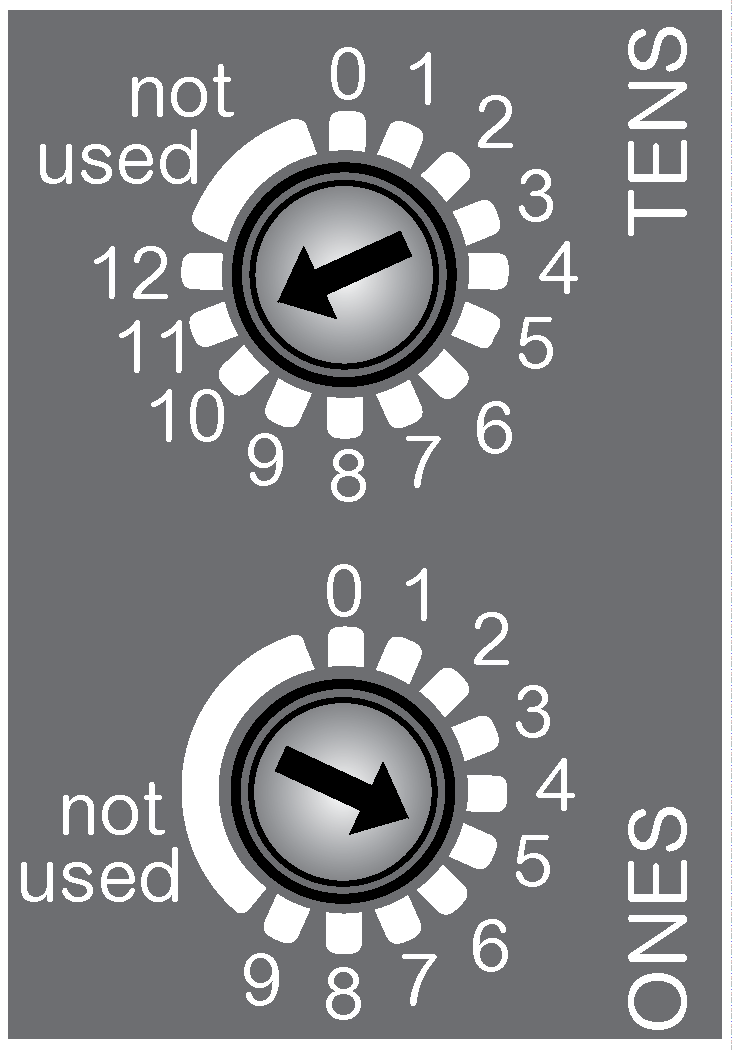
The TM3 CANopen bus coupler address (from 1 to 127, decimal) is configured using the two CANopen address settings rotary switches.
| WARNING | |
|---|---|
To reset the CANopen bus coupler, remove power and provide a correct address before reapplying power to the bus coupler.
Set the CANopen address using the TENS rotary switch to represent the hundreds and tens digit and the ONES rotary switch to represent the units digit.
Carefully manage the addresses because each device on the network requires a unique address. Having multiple devices with the same address can cause unintended operation of your network and associated equipment.
| WARNING | |
|---|---|
