TM3DM24R / TM3DM24RG Characteristics
Introduction
This section provides a description of the electrical and input/output characteristics of the TM3DM24R / TM3DM24RG expansion modules.
See also Environmental Characteristics.
| DANGER | |
|---|---|
| WARNING | |
|---|---|
Dimensions
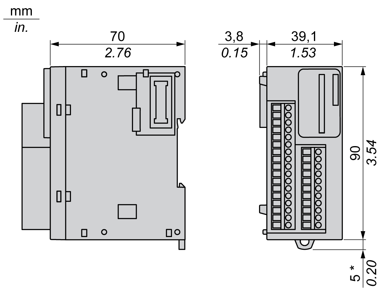
The following diagrams show the external dimensions for the TM3DM24R / TM3DM24RG expansion modules:

Input Characteristics
The table below describes the inputs characteristics of the TM3DM24R / TM3DM24RG:
|
Characteristic |
Value |
||
|---|---|---|---|
|
Number of input channels |
16 inputs |
||
|
Number of channels groups |
1 common line for 16 channels |
||
|
Input type |
Type 1 (IEC/EN 61131-2) |
||
|
Logic type |
Sink/source |
||
|
Rated input voltage |
24 Vdc |
||
|
Input voltage range |
0...28.8 Vdc |
||
|
Rated input current |
7 mA |
||
|
Input impedance |
3.4 kΩ |
||
|
Input limit values |
Voltage at state 1 |
> 15 Vdc (15...28.8 Vdc) |
|
|
Voltage at state 0 |
< 5 Vdc (0...5 Vdc) |
||
|
Current at state 1 |
> 2.5 mA |
||
|
Current at state 0 |
< 1.0 mA |
||
|
Turn on time |
SV (1) < 2.0: 4 ms SV (1) ≥ 2.0: 100 μs (2) |
||
|
Turn off time |
|||
|
Isolation |
Between input and internal logic |
500 Vac |
|
|
Between input group and output group |
1500 Vac |
||
|
Between input groups |
N/A |
||
|
Connection type |
TM3DM24R |
Removable screw terminal block |
|
|
TM3DM24RG |
Removable spring terminal block |
||
|
Connector insertion/removal durability |
Over 100 times |
||
|
Current draw on 5 Vdc internal bus |
42 mA (all inputs and outputs on) |
||
|
5 mA (all inputs and outputs off) |
|||
|
Current draw on 24 Vdc internal bus |
39 mA (all inputs and outputs on) |
||
|
0 mA (all inputs and outputs off) |
|||
|
(1) SV refers to the version and is printed on the product label. (2) The range depends on the configured filter value. If you use EcoStruxure Machine Expert - Basic, refer to the Modicon TM3 (EcoStruxure Machine Expert - Basic) Expansion Modules Configuration - Programming Guide. If you use EcoStruxure Machine Expert, refer to the Modicon TM3 Expansion Modules - Programming Guide. |
|||
Output Characteristics
The table below describes the outputs characteristics of the TM3DM24R / TM3DM24RG:
|
Characteristic |
Value |
|
|---|---|---|
|
Number of output channels |
8 |
|
|
Number of channel groups |
2 common line for 8 channels |
|
|
Output type |
Relay |
|
|
Contact type |
NO (Normally Open) |
|
|
Rated output voltage |
24 Vdc, 240 Vac |
|
|
Maximum voltage |
30 Vdc, 264 Vac |
|
|
Minimum switching load |
5 Vdc at 10 mA |
|
|
Rated output current |
2 A |
|
|
Maximum output current |
2 A per channels |
|
|
7 A per commons |
||
|
Maximum output frequency |
with maximum load |
20 operations per minute |
|
Turn on time |
Max. 10 ms |
|
|
Turn off time |
Max. 10 ms |
|
|
Contact resistance |
30 mW |
|
|
Mechanical life |
20 million operations |
|
|
Electrical life |
Under resistive load |
See Power limitation |
|
Under inductive load |
||
|
Protection against short circuit |
No |
|
|
Isolation |
Between input and internal logic |
500 Vac |
|
Between input group and output group |
1500 Vac |
|
|
Between input groups |
N/A |
|
|
Connection type |
TM3DM24R |
Removable screw terminal block |
|
TM3DM24RG |
Removable spring terminal block |
|
|
Connector insertion/removal durability |
Over 100 times |
|
|
Current draw on 5 Vdc internal bus |
42 mA (all inputs and outputs on) 5 mA (all inputs and outputs off) |
|
|
Current draw on 24 Vdc internal bus |
39 mA (all inputs and outputs on) 0 mA (all inputs and outputs off) |
|
|
NOTE: Refer to Protecting Outputs from Inductive Load Damage for additional information on this topic.
|
||
Power Limitation
This table describes the power limitation of the TM3DM24R / TM3DM24RG expansion modules depending on the voltage, the type of load, and the number of operations required.
These expansion modules do not support capacitive loads.
| WARNING | |
|---|---|
|
Power Limitations |
||||
|---|---|---|---|---|
|
Voltage |
24 Vdc |
120 Vac |
240 Vac |
Number of operations |
|
Power of resistive loads AC-12 |
– |
240 VA 80 VA |
480 VA 160 VA |
100,000 300,000 |
|
Power of inductive loads AC-15 (cos ϕ = 0.35) |
– |
60 VA 18 VA |
120 VA 36 VA |
100,000 300,000 |
|
Power of inductive loads AC-14 (cos ϕ = 0.7) |
– |
120 VA 36 VA |
240 VA 72 VA |
100,000 300,000 |
|
Power of resistive loads DC-12 |
48 W 16 W |
– |
– |
100,000 300,000 |
|
Power of inductive loads DC-13 L/R = 7 ms |
24 W 7.2 W |
– |
– |
100,000 300,000 |
