Programming
Overview
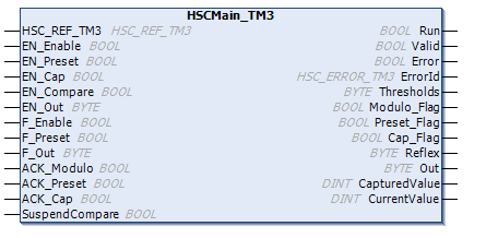
The type is always managed by an HSCMain_TM3 function block.
HSCMain_TM3 function block is used to manage a different HSC type.
Adding the HSCMain Function Block
|
Step |
Description |
|---|---|
|
1 |
Select the tab in the and click . Select in the list. |
|
2 |
Drag-and-drop the item onto the window. |
|
3 |
Edit the default type instance name to match the of the counter function block defined in the Configuration window. |

I/O Variables Usage
For the type, the outputs are automatically activated in case F_Out is activated, even if Valid = FALSE.
| WARNING | |
|---|---|
The tables below describe how the different pins of the function block are used in type.
This table describes the input variables:
|
Input |
Type |
Description |
|---|---|---|
|
|
|
Reference to the HSC instance. |
|
|
|
When input is configured: if |
|
|
|
Not used. |
|
|
|
Not used. |
|
|
|
|
|
|
|
Set bits to 1 to enable corresponding physical outputs to echo the configured function value (Reflex or Stop) as a result of the comparison function. Only active when outputs configured in HSC editor:
Association of HSC output |
|
|
|
|
|
|
|
Not used. |
|
|
|
Set bits to 1 to force corresponding physical outputs to 1 if associated with HSC by configuration. Takes priority over Only active when outputs configured in HSC editor:
Association of HSC output |
|
|
|
Not used. |
|
|
|
Not used. |
|
|
|
Not used. |
|
|
|
NOTE:
EN_Compare, EN_Reflex, and F_Out remain operational while SuspendCompare is set.
|
This table describes the output variables:
|
Outputs |
Type |
Comment |
|---|---|---|
|
|
|
Edge to Edge: Set to 1 at rising edge detection, and reset to 0 at falling edge. Edge to Opposite: Set to 1 at first rising edge detection. It is only reset to 0 if the counter is disabled or an error is detected. |
|
|
|
|
|
|
|
|
|
|
|
Indicates the value of the error detected. See |
|
|
|
Bits set to 1 when CurrentValue ≥ Threshold:
Only active when |
|
|
|
Not used. |
|
|
|
Not used. |
|
|
|
Not used. |
|
|
|
State of the reflex function:
|
|
|
|
State of the physical outputs:
Association of HSC output Outx with physical output Qy is done by configuration. |
|
|
|
Not used. |
|
|
|
The value of the counter. |