Adding an Expansion Module
Adding a Module
To add an expansion module to your controller, select the expansion module in the , drag it to the , and drop it on one of the highlighted nodes.
For more information on adding a device to your project, refer to:
• Using the Drag-and-drop Method
• Using the Contextual Menu or Plus Button
I/O Mapping Tab
The I/O mapping of an expansion module is carried out through the tab of the expansion module configuration.
This table describes how to configure an expansion module:
|
Step |
Action |
|---|---|
|
1 |
Double-click the expansion module node in the to display the tab. |
|
2 |
Edit the parameters of the tab to configure the expansion module. |
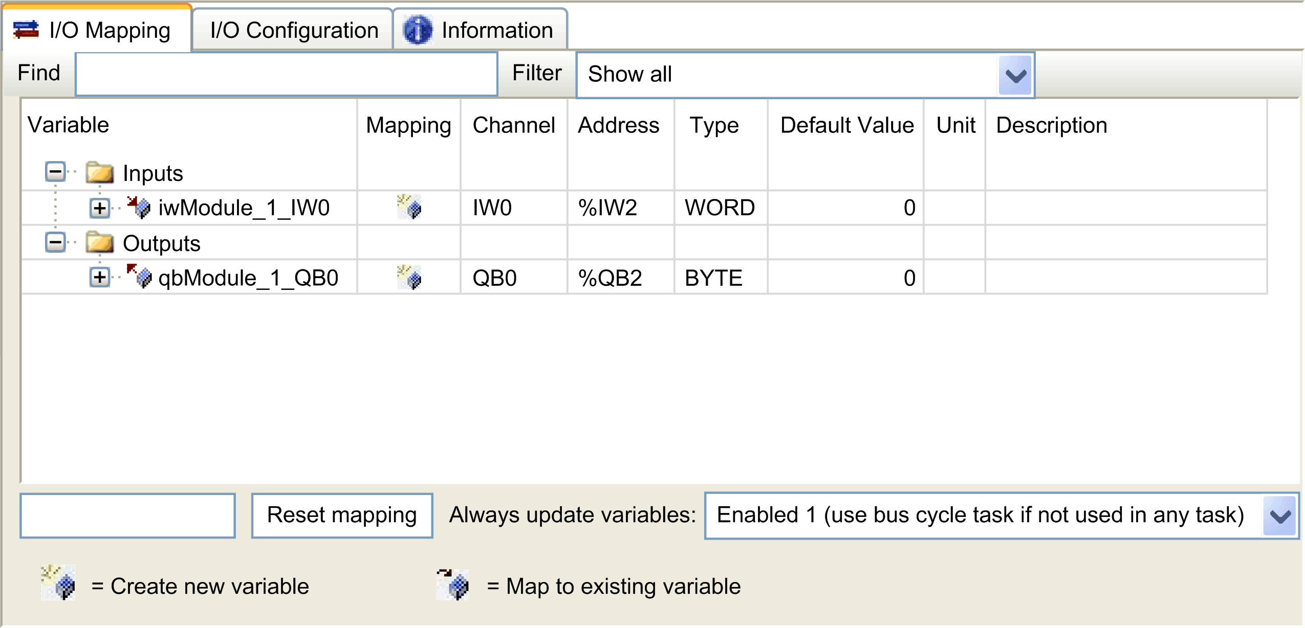
This figure shows the tab:

This table describes each parameter of the tab:
|
Parameter |
Description |
|---|---|
|
|
Allows you to map the channel on a variable.
NOTE: Expand the list of variables from the category or .
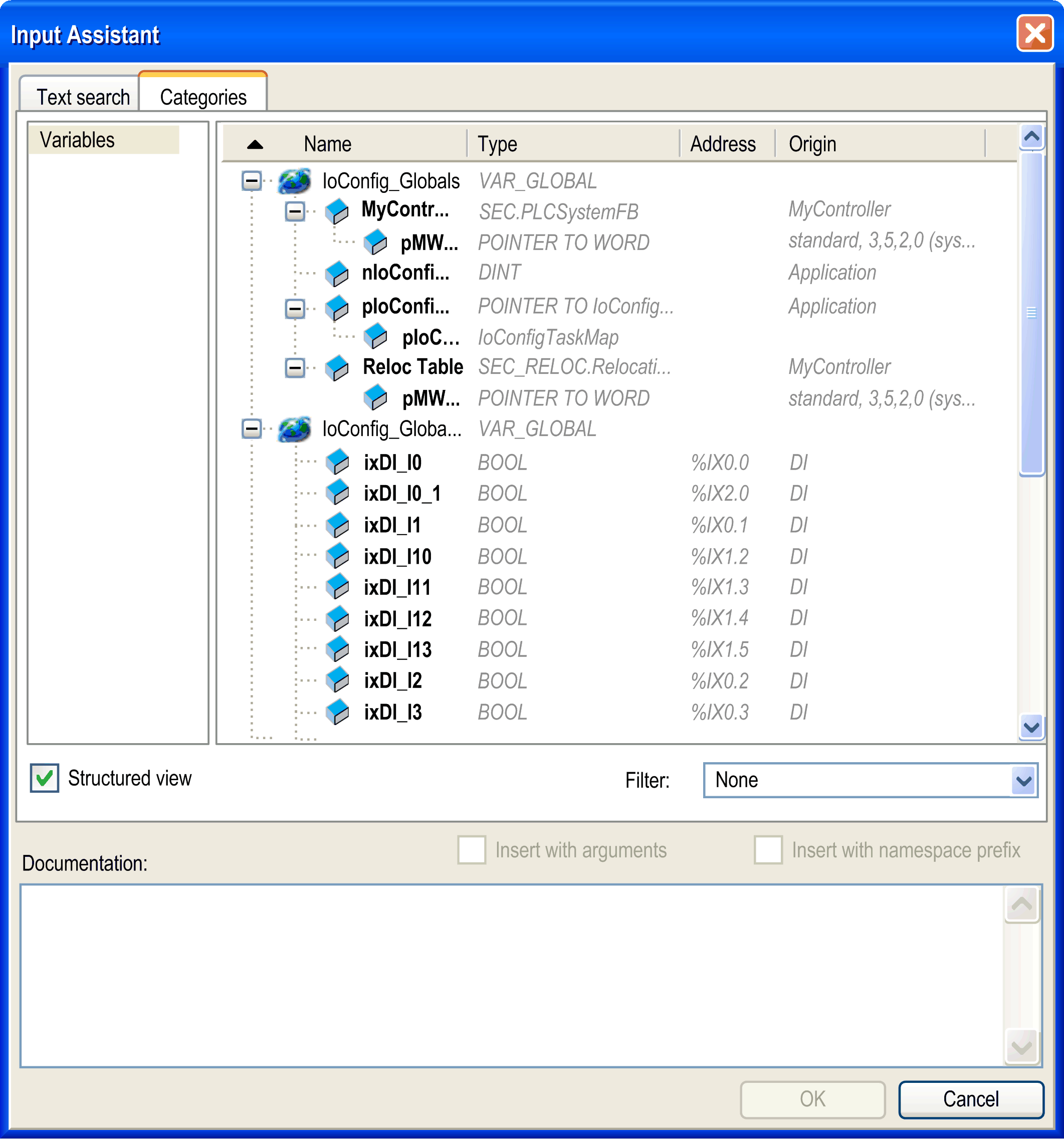
You can map a channel by either creating a new variable or mapping to an existing variable. : Double-click the variable to enter the new variable name. A new variable is created if the variable does not already exist. : Double-click the variable and click to open the window. Select the variable from the list and press . This figure shows the window: 
|
|
|
Indicates whether the channel is mapped on a new variable or an existing variable. |
|
|
Displays the channel name of the device. |
|
|
Displays the address of the channel.
NOTE: If the channel is mapped to an existing variable, corresponding address appears as strikethrough text in the table.
|
|
|
Displays the data type of the channel. |
|
|
Indicates the value taken by the output when the controller is in a or state. Double-click the cell to change the default value. You can toggle between the following values:
|
|
|
Displays the unit of the channel value. |
|
|
Allows you to enter a short description of the channel. |
|
|
Depending on the controller reference, you can configure the . This configuration setting is the parent for all parameters used in the application device tree. Some devices with cyclic calls, such as a , can be attached to a specific task. In the device, when this setting is set to , the setting set for the controller is used. The selection list offers all tasks currently defined in the active application. The default setting is . |
I/O Configuration Tab
This tab allows you to configure the I/O module:

Configuring the Latch and Filter Parameters
You can select the type of edge for the latch parameter, refer to Latch Principles:
-
Rising edge
-
Falling edge
-
Both edge
-
None
The filter parameter reduces the effect of bounce on a controller digital input.
You can configure these parameters on the following modules:
-
TM3DI• except TM3DI8A
-
TM3DM•
except TM3DM16R and TM3DM32R -
TM3XHSC202 / TM3XHSC202G and TM3XFHSC202 / TM3XFHSC202G
This table describes how to configure the latch and filter parameters.
|
Step |
Action |
|---|---|
|
1 |
Click the module node tab. |
|
2 |
Select as for . |
|
3 |
Select an input. |
|
4 |
Configure the parameters. |
This table describes the latch and filter parameters:
|
|
|
|
|
|
|---|---|---|---|---|
|
|
|
*
|
– |
allows you to configure latch and filter parameters. |
|
|
||||
|
|
|
*
|
– |
Latching allows incoming pulses with amplitude widths shorter than controller scan time to be captured and recorded.
NOTE: is not supported when the expansion module is used with a Modicon TM3 Bus Coupler.
|
|
|
|
*
|
ms |
Integrator filtering value reduces the effect of bounce on a controller input.
NOTE: TM3XHSC202 / TM3XHSC202G expansion modules have different filter values, see Configuration of Inputs.
NOTE: TM3XFHSC202 / TM3XFHSC202G expansion modules have different filter values, see Configuration of Inputs.
|
|
* Parameter default value |
||||
Configuring the Outputs
This table describes how to configure the fallback parameters:
|
Step |
Action |
|---|---|
|
1 |
Click the module node tab. |
|
2 |
Select as for . |
|
3 |
Select an output. |
|
4 |
Configure the parameters. |
This table presents the function of the different parameters:
|
Parameter |
Value |
Description |
|
|---|---|---|---|
|
|
*
|
Allows you to set the fallback mode when the connection between the controller and the module is lost. |
|
|
|
0* 1 |
Allows you to set the force value. Only available if the is set to . |
|
|
* Parameter default value |
|||
-
TM3XHSC202 / TM3XHSC202G, refer to Configuration of Outputs
-
TM3XFHSC202 / TM3XFHSC202G, refer to Configuration of Outputs