TM3TI8T / TM3TI8TG
Introduction
The TM3TI8T (screw terminal block) / TM3TI8TG (spring terminal block) expansion module feature 8 analog input channels with 16-bit resolution.
The channel input types are:
-
K thermocouple
-
J thermocouple
-
R thermocouple
-
S thermocouple
-
B thermocouple
-
E thermocouple
-
T thermocouple
-
N thermocouple
-
C thermocouple
-
NTC thermistor
-
PTC thermistor
-
Ohmmeter
For information on the diagnostic codes produced by each input type, refer to Analog I/0 Modules Diagnostics.
For further hardware information, refer to TM3TI8T / TM3TI8TG.
If you have physically wired the analog channel for a voltage signal and you configure the channel for a current signal in EcoStruxure Machine Expert, you may damage the analog circuit.
| NOTICE | |
|---|---|
Configuring the Module
For each input, you can define the following parameters:
|
Parameter |
Value |
Default Value |
Description |
|
|---|---|---|---|---|
|
|
- |
|
Choose the parameter type and scope for the channel. |
|
|
|
|
|
||
|
|
|
|
||
|
|
|
|
||
|
|
|
|
||
|
|
See the table below |
Specifies the low measurement limit. |
||
|
|
See the table below |
Specifies the high measurement limit. |
||
|
(used only with NTC probe) |
1...65535 |
330 |
Reference resistance in Ohm at temperature Tref. |
|
|
(used only with NTC probe) |
1...1000 |
25 |
Reference temperature value in Celsius. |
|
|
(used only with NTC probe) |
1...32767 |
3569 |
Sensitivity of NTC probe in Kelvin. |
|
|
|
0...1000 |
0 |
Specifies the first order filter time constant (0...10 s) in increments of 10 ms. |
|
|
|
|
|
Specifies the sampling period of the channel. |
|
|
|
|
|
Enables the diagnostic byte of each channel.
If the status is disabled (value = No), the status bytes |
|
|
(used only with PTC probe) |
100...10000 |
3100 |
Activation threshold |
|
|
(used only with PTC probe) |
100...10000 |
1500 |
Reactivation threshold |
|
The following table indicates the possible range values for the selected type of thermocouple:
|
Type |
Customized |
Range in Celsius |
Range in Fahrenheit |
|---|---|---|---|
|
K Thermocouple |
-32768...32767 |
-2000...13000 (0.1°C) |
-3280...23720 (0.1°F) |
|
J Thermocouple |
-2000...10000 (0.1°C) |
-3280...18320 (0.1°F) |
|
|
R Thermocouple |
0...17600 (0.1°C) |
320...32000 (0.1°F) |
|
|
S Thermocouple |
0...17600 (0.1°C) |
320...32000 (0.1°F) |
|
|
B Thermocouple |
0...18200 (0.1°C) |
160...16540 (0.2°F) |
|
|
E Thermocouple |
-2000...8000 (0.1°C) |
-3280...14720 (0.1°F) |
|
|
T Thermocouple |
-2000...4000 (0.1°C) |
-3280...7520 (0.1°F) |
|
|
N Thermocouple |
-2000...13000 (0.1°C) |
-3280...23720 (0.1°F) |
|
|
C Thermocouple |
0...23150 (0.1°C) |
160...20995 (0.2°F) |
|
|
NTC Thermistor |
-900...1500 (0.1°C) |
-1300...3020 (0.1°F) |
|
|
PTC Thermistor |
– |
– |
NTC Thermistor
The temperature (Tm) varies in relation to the resistance (r) following the equation below:

Where:
-
Tm = temperature measured by the probe, in Kelvin
-
r = physical value of the resistance in Ohm
-
R = reference resistance in Ohm at temperature T
-
T = reference temperature in Kelvin
-
B = sensitivity of the NTC probe in Kelvin
R,T, and B must be greater or equal to 1.
PTC Thermistor
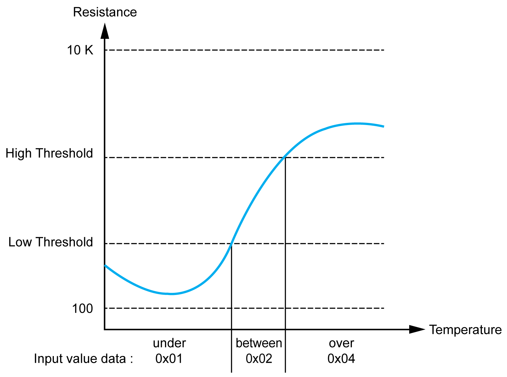
This table describes the read value according to the resistance:
|
Resistance Value |
Read Value |
|---|---|
|
Under the low threshold |
1 |
|
Between thresholds |
2 |
|
Over the high threshold |
4 |
This figure represents the threshold operation:

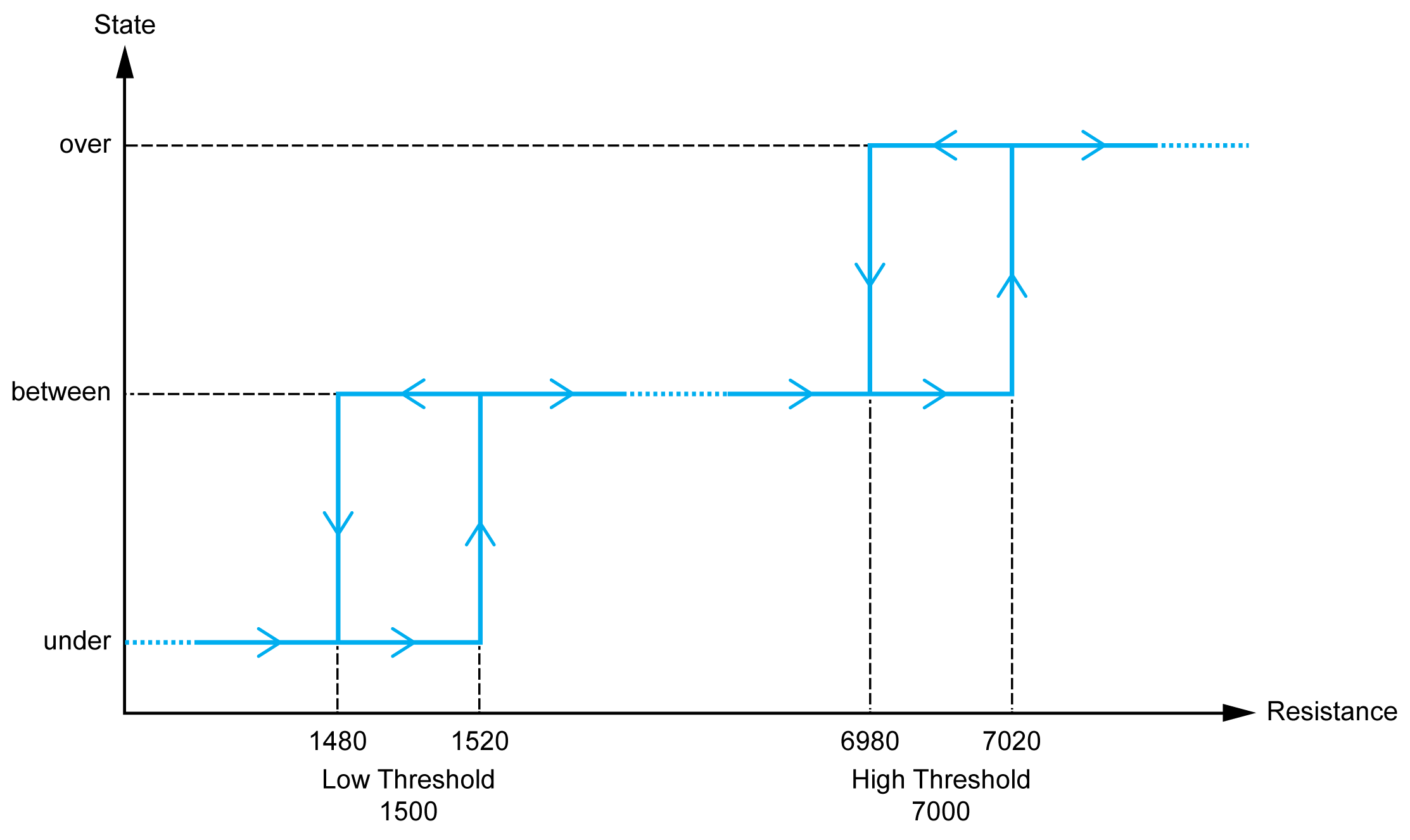
This figure represents an example hysteresis curve:

Ohmmeter
This table describes the minimum and maximum values:
|
Parameter |
Value |
|---|---|
|
Minimum |
100 Ω |
|
Maximum |
32 kΩ |
I/O Mapping Tab
Variables can be defined and named in the tab. Additional information such as topological addressing is also provided in this tab.
This table describes the tab:
|
Variable |
Channel |
Type |
Description |
|---|---|---|---|
|
Inputs |
IW0 |
INT |
Current value of the input 0 |
|
IW1 |
INT |
Current value of the input 1 |
|
|
IW2 |
INT |
Current value of the input 2 |
|
|
IW3 |
INT |
Current value of the input 3 |
|
|
IW4 |
INT |
Current value of the input 4 |
|
|
IW5 |
INT |
Current value of the input 5 |
|
|
IW6 |
INT |
Current value of the input 6 |
|
|
IW7 |
INT |
Current value of the input 7 |
|
|
Diagnostic |
IBStatusIW0 |
BYTE |
|
|
IBStatusIW1 |
BYTE |
||
|
IBStatusIW2 |
BYTE |
||
|
IBStatusIW3 |
BYTE |
||
|
IBStatusIW4 |
BYTE |
||
|
IBStatusIW5 |
BYTE |
||
|
IBStatusIW6 |
BYTE |
||
|
IBStatusIW7 |
BYTE |
For further generic descriptions, refer to I/O Mapping Tab Description.